Endplay adjustment and bearing decoupling in an electric motor

a technology of bearing decoupling and endplay, which is applied in the direction of sliding contact bearings, mechanical energy handling, mechanical equipment, etc., can solve the problems of contributing to the overall motor noise and causing bearing/structure nois

Inactive Publication Date: 2005-01-27
SIEMENS VDO AUTOMOTIVE INC
View PDF3 Cites 14 Cited by
  • Summary
  • Abstract
  • Description
  • Claims
  • Application Information

AI Technical Summary

Benefits of technology

[0009] An object of the invention is to fulfill the need referred to above. In accordance with the principles of the present invention, this objective is achieved by providing an electric motor having an armature structure including a shaft, and frame structure. At least one sleeve bearing is operatively associated with an end of the shaft to support the shaft for rotation, and a unitary bearing retainer structure is coupled with the frame structure and holds the sleeve bearing. The retainer structure is constructed and arranged 1) to prevent movement of the retainer structure in a direction towards the end of the shaft, 2) to provide a spring force against the frame structure to prevent the retainer structure from moving in a direction away from the end of the shaft, and 3) to control endplay of the armature structure by controlling engagement of the retainer structure with the frame structure.

Problems solved by technology

In any rotating electrical device bearing noise is a significant contributor to the overall motor noise.
Bearing / structure noise is created by vibration transferred to the adjacent resonating structure.

Method used


Image

  • Endplay adjustment and bearing decoupling in an electric motor
  • Endplay adjustment and bearing decoupling in an electric motor
  • Endplay adjustment and bearing decoupling in an electric motor

Examples


Embodiment Construction

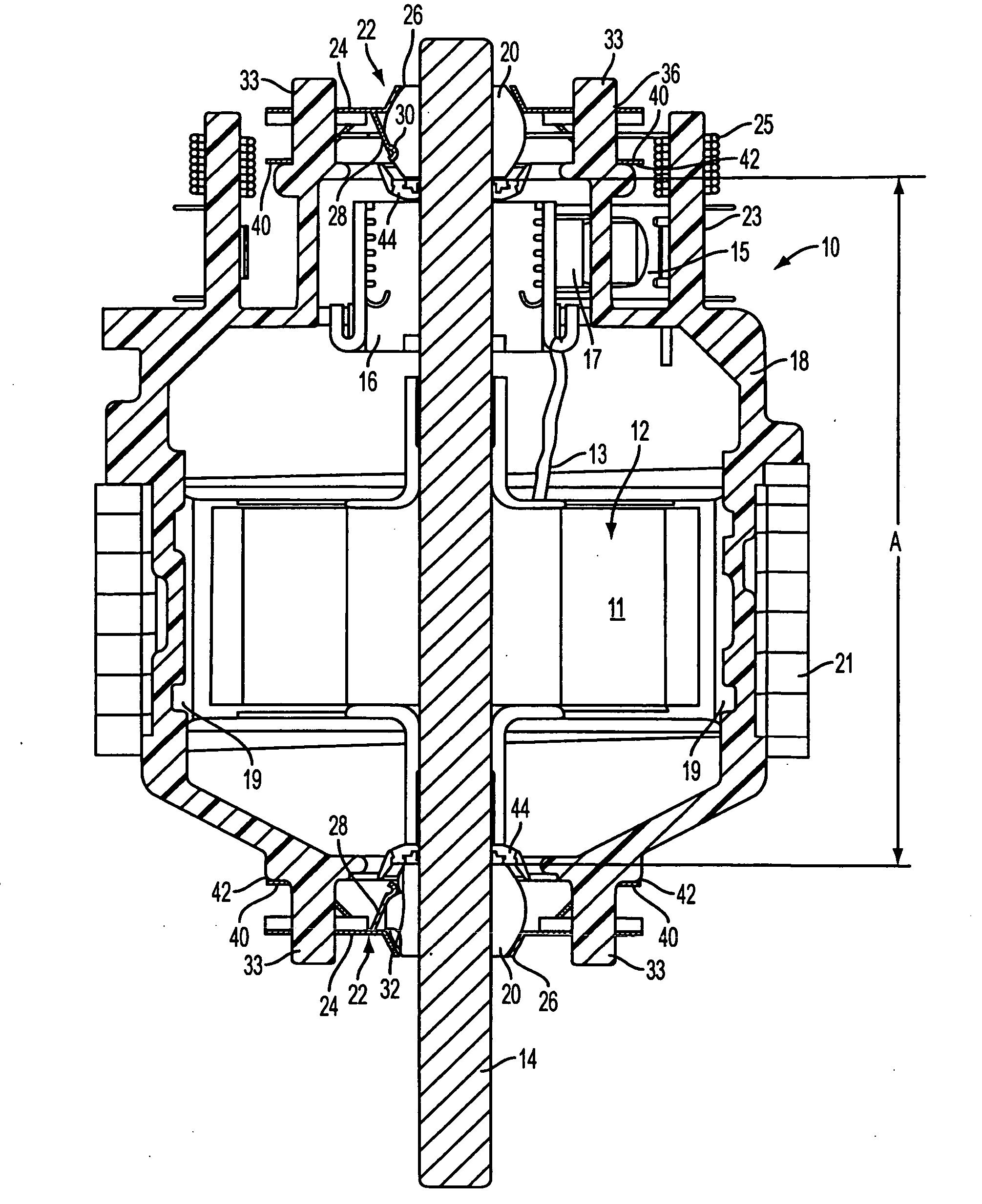
[0016] With reference to FIG. 1, an electric motor is shown, generally indicated at 10, in accordance with the principles of the invention. The motor 10 is preferably configured for automotive HVAC systems. The electric motor 10 includes an armature structure, generally indicated at 12. The armature structure 12 includes a lamination stack 11 carrying windings 13 (the complete set of windings is not shown in the interest of clarity of FIG. 1). The armature structure 12 also includes a shaft 14 and a commutator 16 coupled with the shaft 14. Brushes 17 engage the commutator 16 and conduct electrical current to the windings 13 which are connected to the commutator 16. Each brush 17 is carried by a brush arm 15 that is coupled to a support 23 of the frame structure 18 of the motor 10. A spring 24 biases the brush arm 15 and thus brush 17 into contact with the commutator 16. Two permanent magnets 19 are disposed adjacent to the lamination stack 11 and are carried by the frame structure 1...


PUM


Abstract

An electric motor 10 has an armature structure 12 including a shaft 14, a lamination stack 11 coupled with the shaft, a commutator 16 coupled with the shaft, and windings 13 carried by the lamination stack and connected to the commutator. Brushes 17 engage the commutator to deliver electric current to the windings. The motor includes a frame structure 18 carrying permanent magnets 19, at least one sleeve bearing 20 operatively associated with an end of the shaft to support the shaft for rotation, and a unitary bearing retainer structure 22 coupled with the frame structure and holding the at least one sleeve bearing. The retainer structure is constructed and arranged 1) to prevent movement of the retainer structure in a direction towards the end of the shaft, 2) to provide a spring force against the frame structure to prevent the retainer structure from moving in a direction away from the end of the shaft, and 3) to control endplay of the armature structure by controlling engagement of the retainer structure with the frame structure.

Description

[0001] This application is based on U.S. Provisional Application No. 60 / 490,306, filed on Jul. 25, 2003, and claims the benefit thereof for priority purposes.FIELD OF THE INVENTION [0002] The invention relates to a sleeve bearing assembly of an electric motor for reducing bearing noise and for adjusting endplay of an armature of the motor. BACKGROUND OF THE INVENTION [0003] In any rotating electrical device bearing noise is a significant contributor to the overall motor noise. In an electric motor with one or two sleeve bearings that are used for both axial thrust surfaces and cylindrical running surfaces, the bearing related noise consists of four main components: [0004] 1) Bearing / Shaft Friction Noise created by the interface of two sliding surfaces [0005] 2) Commutator Brush Noise / vibration transmitted through the commutator to the shaft to the bearing [0006] 3) Cogging Torque Noise transmitted from the cogging lamination in the magnetic circuit to the shaft to the bearing [0007]...

Claims


Application Information

Patent Timeline
Patent Type & Authority Applications(United States)
IPC IPC(8): F16C27/02F16C33/08H02K5/167H02K5/24
CPCF16C27/02H02K5/24H02K5/1672F16C33/08
Inventor SIMPSON, STANFISHER, BRYAN TODD
Owner SIEMENS VDO AUTOMOTIVE INC
Why Eureka
Try Eureka