Ring structures in optical fibres

a technology of optical fibres and rings, applied in the field of optical components, can solve the problems of reducing fringe contrast, polarisation of light in the fibre to fluctuate, and affecting the performance of optical fibres, and achieve the effect of high refractive index contras

Inactive Publication Date: 2005-01-27
THE UNIV OF SYDNEY
View PDF9 Cites 35 Cited by
  • Summary
  • Abstract
  • Description
  • Claims
  • Application Information

AI Technical Summary

Problems solved by technology

However, these fibres are subject to a number of inherent limitations and disadvantages.
Consequently, imperfections and bends in the fibre, manufacturing flaws as well as environmental disturbances can cause the polarisation of light in the fibre to fluctuate.
This is a significant disadvantage in optical sensing applications, for example, due to the reduction in fringe contrast resulting from changes in polarisation.
It also causes problems in optical data transmission applications due to polarisation mode dispersion.
In practice, however, Bragg fibres have not been used in this context to any great extent, because the range of refractive index contrasts achievable between adjacent layers formed from known materials, using existing production techniques, is either relatively small so that a very large number of layers is needed, or is relatively large with the restriction that the materials are incompatible and the structure can not be effectively drawn into an optical fibre.

Method used


Image

  • Ring structures in optical fibres
  • Ring structures in optical fibres

Examples


Embodiment Construction

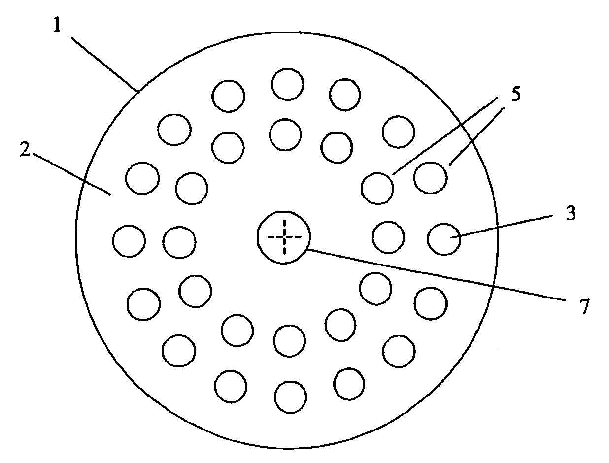
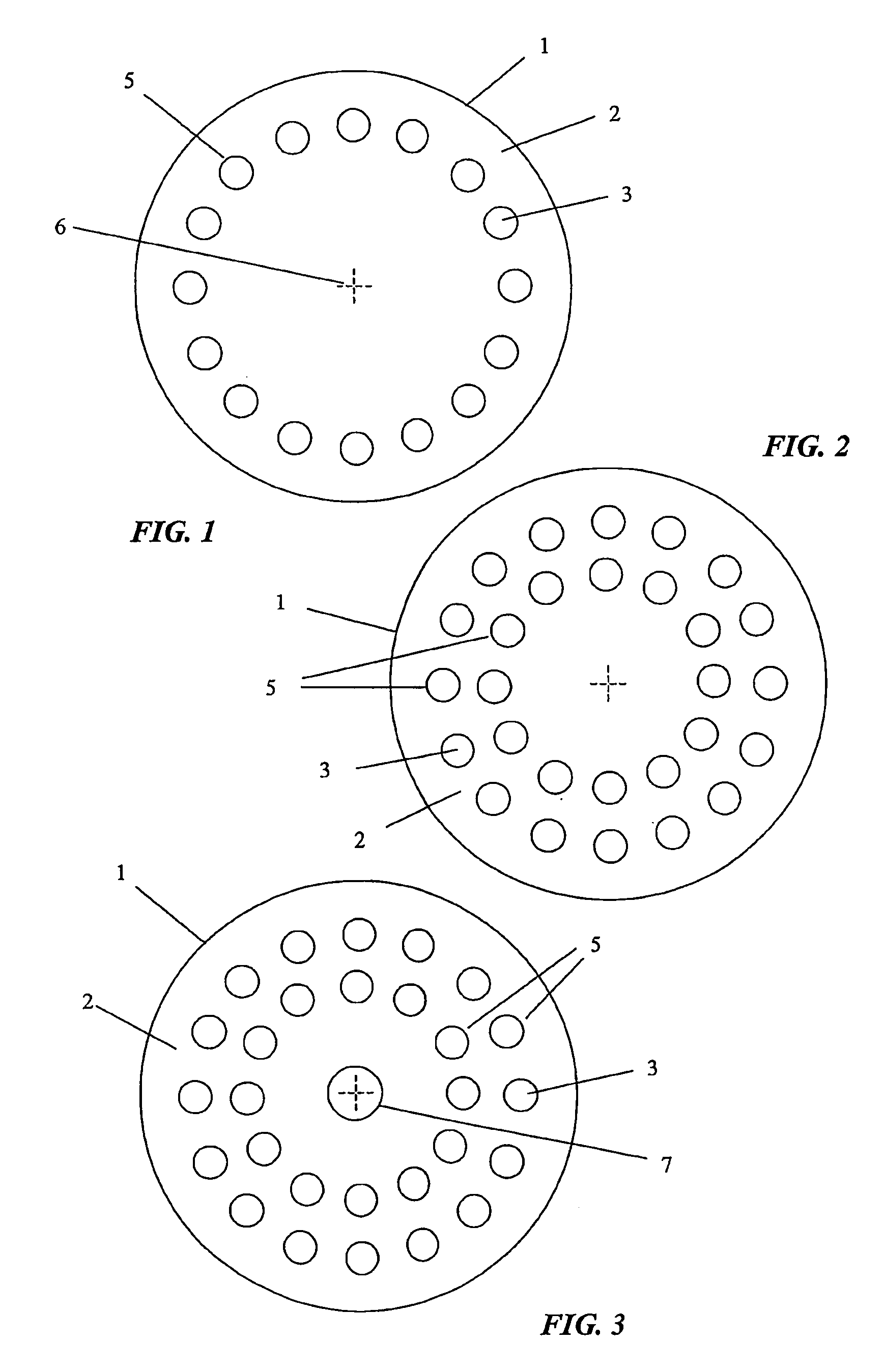
[0016] Referring to the drawings, the invention provides an optical fibre 1 incorporating a body 2, and a plurality of longitudinally extending holes or inclusions 3 formed in the body. In the arrangement shown in FIG. 1, the holes are disposed in a circular array to define a ring structure 5 extending coaxially around a longitudinal axis 6 of the body of the fibre.

[0017] In one preferred configuration, the main body of the fibre is formed substantially from an optical polymeric material, and the inclusions 3 defining the ring structure 5 are substantially filled with air. Advantageously, this approach allows a relatively high refractive index contrast between the fibre material, which has a typical refractive index of around 1.5) and the entrained air, which has a refractive index of 1.0. It should be appreciated, however, that the inclusions may alternatively contain other materials, such as silica or polymers having different chemical compositions, densities or refractive indice...


PUM


Abstract

This invention provides an optical fibre (1) incorporating a body (2), and an array of longitudinally extending holes or inclusions (3) formed in the body (2), the holes or inclusions (3) having a different refractive index from the surrounding body (2) and being arranged to form a full or partial ring structure (5) extending generally around a longitudinal axis of the fibre, the ring structure (5) being disposed so as to approximate the refractive or reflective transmission characteristics of a multi-layer optical fibre. The fibre (1) may have a solid core or a hollow air core. The invention also provides a method of forming the microstructured optical fibre (1).

Description

FIELD OF THE INVENTION [0001] The present invention relates generally to optical components. [0002] The invention has been developed primarily for use in photonics, and will be described predominantly with reference to this application. It will be appreciated by those skilled in the art, however, that the invention is not limited to this particular field of use. BACKGROUND OF THE INVENTION [0003] Conventional optical fibres operate through total internal reflection (TIR) from a refractive index profile of the type incorporated, for example, in step-index or graded index fibres. These fibres have been manufactured from a variety of materials, including silica glass and various types of polymers. However, these fibres are subject to a number of inherent limitations and disadvantages. [0004] For instance, a single mode step index fibre is strictly speaking not single moded; as there are still two degrees of freedom, corresponding to the two polarisation states. Consequently, imperfecti...

Claims


Application Information

Patent Timeline
Patent Type & Authority Applications(United States)
IPC IPC(8): G02B6/02G02B6/032G02B6/036
CPCG02B6/02G02B6/032G02B6/02366G02B6/02361
Inventor ARGYROS, ALEXANDERLARGE, MARYANNE CANDIDA JANESCEATS, MARK GEOFFREYVAN EIJKELENBORG, MARTIJN ALEXANDERBASSETT, IAN MASSON
Owner THE UNIV OF SYDNEY
Why Eureka
Try Eureka