Fuel cell and electric apparatus

a technology of fuel cell and electric equipment, applied in the direction of fuel cells, regenerative fuel cells, cell components, etc., can solve the problems of increasing power consumption, difficult to obtain a primary battery that can supply sufficient energy, and difficult to use a secondary battery at once anytime and anywher

Inactive Publication Date: 2005-01-27
CANON KK
View PDF2 Cites 34 Cited by
  • Summary
  • Abstract
  • Description
  • Claims
  • Application Information

AI Technical Summary

Benefits of technology

[0037] Further, it is preferable that the pore diameter of a porous material of the porous layer gradually becomes smaller in a direction in which water generated in the oxidizer electrode is to be moved and the pore density is uniform.

Problems solved by technology

However, due to recent improved performance of compact electric equipments, power consumption has become greater, making it difficult to obtain a primary battery that can supply sufficient energy while being compact and lightweight.
Further, recharging a secondary battery requires a separate power source and generally takes several ten minutes to several hours, so that it is difficult to use a secondary battery at once anytime and anywhere.
Although it is expected that in future, the electric equipments become smaller and lighter and the wireless network environment is developed thus increasing the tendency to use of portable equipments, it will be difficult for conventional primary and secondary batteries to supply sufficient energy for driving equipments.
However, the ionic conductivity, which determines the performance of a polymer electrolyte fuel cell system, is greatly affected by the wettability of the polymer electrolyte membrane, and in particular, the conductivity dramatically drops due to drying of the polymer electrolyte membrane, so that an increase in the internal resistance will considerably degrade the characteristics of the fuel cell system.
However, in fuel cell system constructions such as described above, when the fuel cell system is large, methods which humidify the fuel gas with water generated during power generation require a pump for transporting the generated water, because the fuel cell is distant from the fuel supply unit.
When a pump is used, a power has to be supplied with the fuel cell system, so that such a system has the disadvantages of their entire structure becoming larger and more complex.
Even for small fuel cell systems, when water generated in an oxidizer electrode is supplied to a fuel passage on a fuel electrode side, it is difficult to prevent the oxidizer from mixing with the fuel.
Because an oxidizer passage at the oxidizer electrode is narrow, unless the generated water is removed the passage is closed off by water droplets, whereby the oxidizer cannot be efficiently led to the oxidizer electrode.
However, in these methods it was difficult to quickly remove water generated in an oxidizer electrode.
These methods also suffered from the problem that when an attempt was made to lead the generated water in a certain direction, an apparatus using an electric power such as a pump or blower was required, thus enlarging the system.
For this reason, it was also difficult to store the used water in a given place.

Method used


Image

  • Fuel cell and electric apparatus
  • Fuel cell and electric apparatus
  • Fuel cell and electric apparatus

Examples


example 1

[0087] A first aspect according to the present invention will be explained in detail while referring to the drawings.

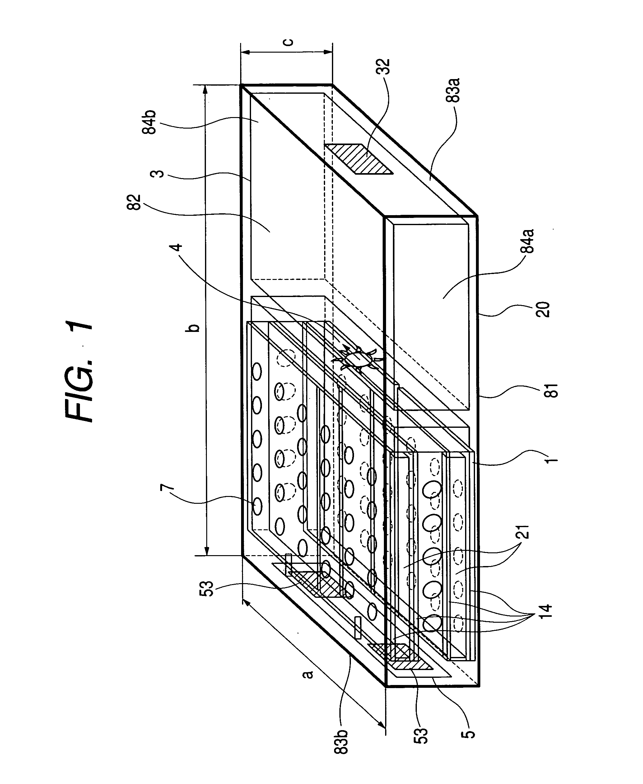
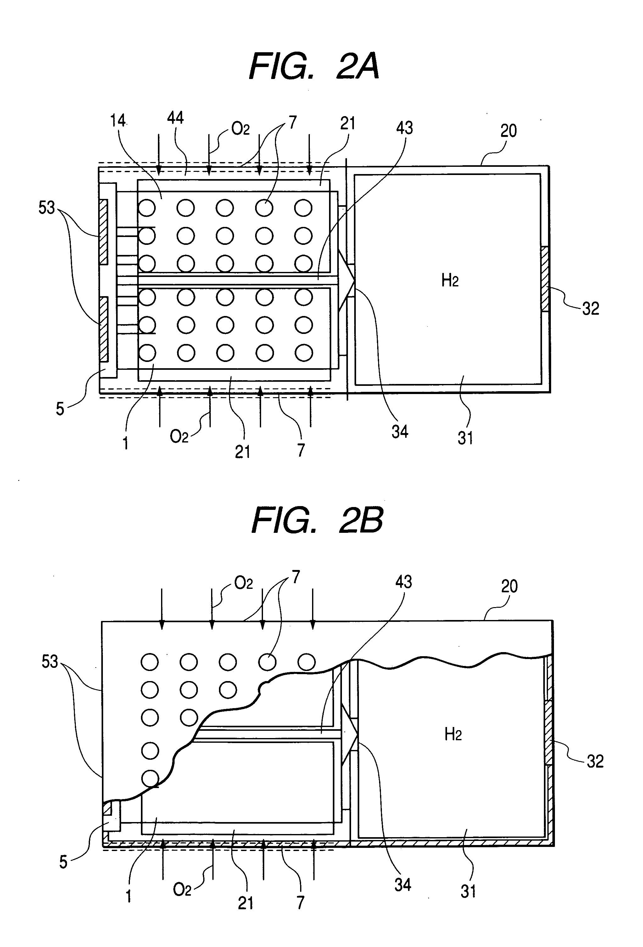
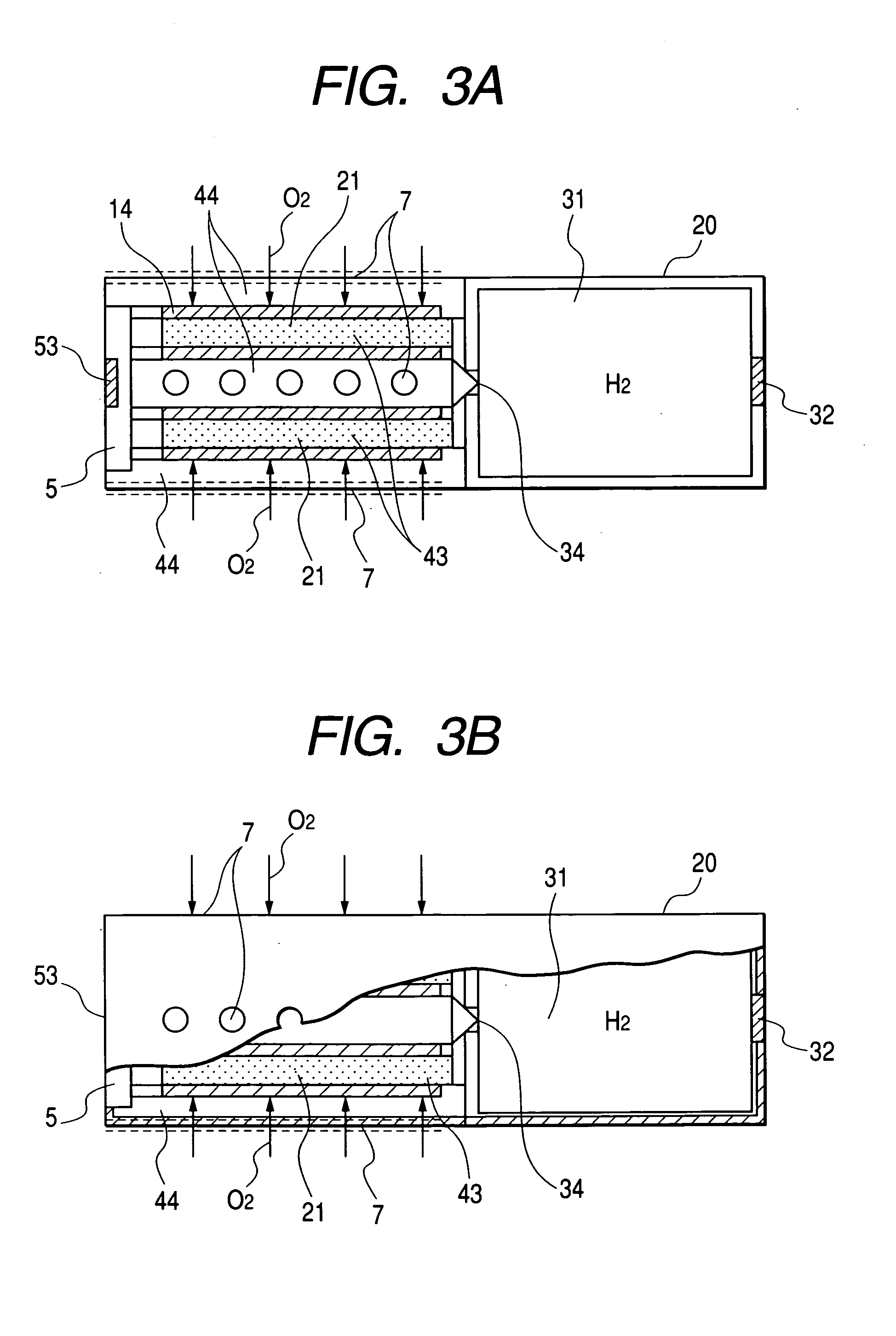
[0088]FIG. 1 is a perspective view illustrating a fuel cell system according to Example 1 of the present invention; FIG. 2A is a plan view of a fuel cell system of FIG. 1; FIG. 2B is a partial cross-sectional plan view of the fuel cell system of FIG. 1; FIG. 3A is a front view of the fuel cell system of FIG. 1; FIG. 3B is a partial cross-sectional front view of the fuel cell system of FIG. 1; FIG. 4 is a left side view of the fuel cell system of FIG. 1; and FIG. 5 is a schematic view showing a structure of the fuel cell system according to the present invention. FIGS. 1, 2A, 3A and 4 illustrate the interior of the fuel cell system as it might be seen through a transparent casing 20.

[0089] Giving one example of the external dimensions of a fuel cell system according to the present invention illustrated in FIG. 1, the length (a) is 30 mm, the width (b) is 50 mm and th...

example 2

[0111] The second aspect of the present invention will be explained in detail while referring to the drawings. Example 2 is a fuel cell system that comprises a cell unit having a water-moving pattern (water-moving means) provided on a surface of an oxidizer electrode, and is of a configuration such that no humidification water passage is provided. Example 2 is the same as Example 1 with the exception that no humidification water passage is provided. FIG. 1 is a perspective view illustrating a fuel cell system in accordance with Example 2 of the present invention. FIG. 2 is plan views of the fuel cell system of FIG. 1. FIG. 3 is front views of the fuel cell system of FIG. 1. FIG. 4 is a left side view of the fuel cell system of FIG. 1. FIG. 5 is a schematic view showing a structure of a fuel cell system according to the present invention.

[0112] Giving one example of the external dimensions of a fuel cell system according to the present example illustrated in FIG. 1, the length (a) i...


PUM

PropertyMeasurementUnit
heightaaaaaaaaaa
widthaaaaaaaaaa
lengthaaaaaaaaaa

Abstract

A fuel cell system is provided which has a humidifying means (2) for directly humidifying a polymer electrolyte membrane (12) that serves as an ionic conductor. As the humidifying means (2), means is employed which has a water holding unit (21) comprised of a water-absorbing material and located in contact with the polymer electrolyte membrane to directly humidify the polymer electrolyte membrane (12) by utilizing a capillary action and further has a humidification water passage (28) comprised of a hydrophilic material and provided in the polymer electrolyte membrane so as to be connected to the water holding unit (21) to humidify the polymer electrolyte membrane (12) rapidly and uniformly. Such a constitution provides a fuel cell system that can directly humidify an ionic conductor.

Description

TECHNICAL FIELD [0001] The present invention relates to a fuel cell system and an electric equipment. BACKGROUND ART [0002] Conventionally, a variety of primary and secondary batteries have been employed for use with portable compact electric equipments. However, due to recent improved performance of compact electric equipments, power consumption has become greater, making it difficult to obtain a primary battery that can supply sufficient energy while being compact and lightweight. On the other hand, although a secondary battery has the advantage that it can be repeatedly recharged and used, the amount of energy that is usable with a single charging is even less than that of a primary battery. Further, recharging a secondary battery requires a separate power source and generally takes several ten minutes to several hours, so that it is difficult to use a secondary battery at once anytime and anywhere. Although it is expected that in future, the electric equipments become smaller an...

Claims


Application Information

Patent Timeline
Patent Type & Authority Applications(United States)
CPCH01M8/04119H01M8/04126Y02E60/50H01M2008/1095H01M8/04171
Inventor NAKAKUBO, TORUEGUCHI, KENWATANABE, MITSUHIRO
Owner CANON KK
Why Eureka
Try Eureka