System and method for coding information on a biosensor test strip
- Summary
- Abstract
- Description
- Claims
- Application Information
AI Technical Summary
Benefits of technology
Problems solved by technology
Method used
Image
Examples
first embodiment
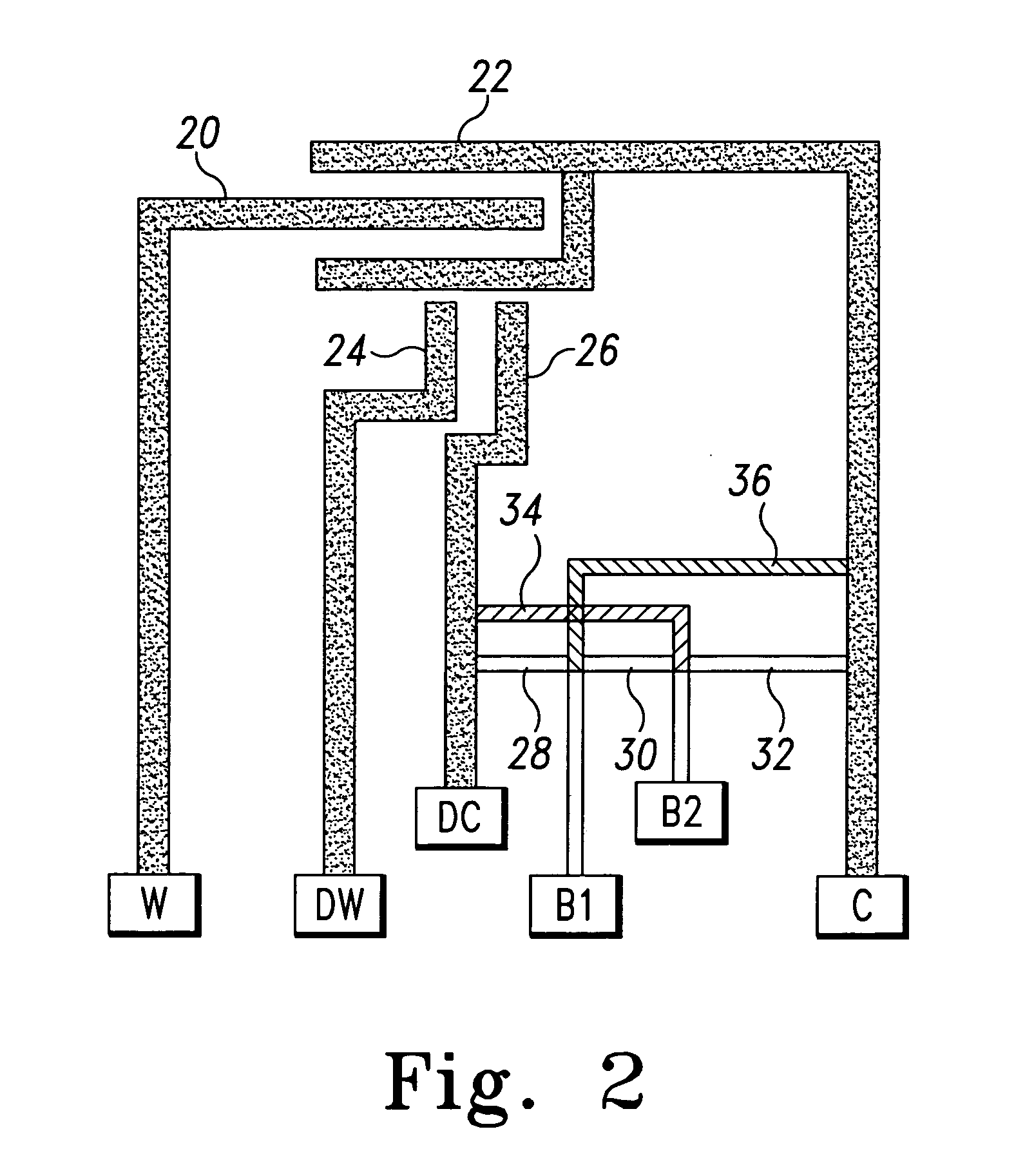
[0039] In the present invention, information about the test strip can be coded directly onto the test strip by the addition of two or more contact pads dedicated to reading such coded information. As illustrated in FIG. 2, a pair of additional information contact pads B1 and B2 are added to the proximal end of the test strip. Additionally, potential conductive links between the information contact pads B1 and B2 and between them and measurement contact pads connected to test strip measurement electrodes are identified at 28, 30, 32, 34 and 36. These links are denominated as potential conductive links because they may either be present or absent in the finished test strip, depending upon the information that is to be coded onto the test strip. Therefore, a “potential conductive link” indicates a conductive link that is found on some, but not all, of a group of otherwise substantially identical test strips. As used herein, the phrase “information contact pad” is defined as a contact p...
second embodiment
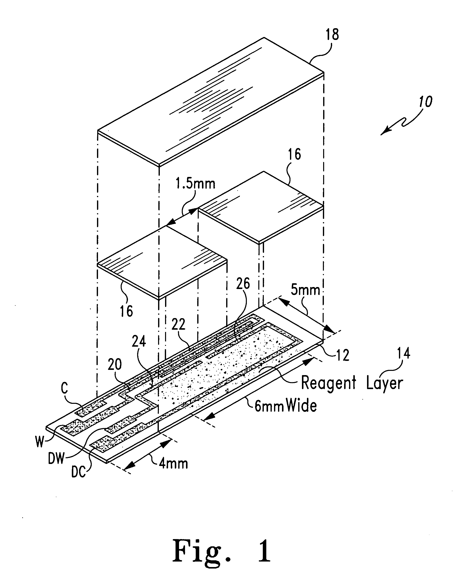
[0075] A second embodiment test strip configuration that allows information to be encoded directly onto the test strip is illustrated in FIG. 10 and indicated generally at 300. The test strip 300 may preferably be formed generally as described above with respect to the test strips 10 and 401, with working 320, counter 322, dose sufficiency working 324, and dose sufficiency counter 326 electrodes may be formed as shown and coupled, respectively, to measurement contact pads W, C, DW and DC. These contact pads provide a conductive area upon the test strip 300 to be contacted by an electrical connector contact of the test meter once the test strip 300 is inserted into the test meter. The test strip may be formed with a sample inlet in the distal end of the test strip (as shown in FIG. 10), or with a sample inlet on the side of the test strip as shown in FIG. 1. The functionality of the information encoding portion thereof is not affected by the positioning of the measurement electrodes ...
third embodiment
[0080] The laser ablation process described hereinabove allows for resolution of test strip conductive features not previously achievable using prior art techniques such as screen printing and photolithography. Because of this, relatively large quantities of data can be coded onto the test strip when the conductive features are formed using the laser ablation process. For example, the present invention is illustrated in FIG. 11 and indicated generally at 500. The test strip 500 is similar to the test strip 300 of FIG. 10, except that the resolution of the laser ablation process allows for an even greater number of contact pads to be formed on the test strip. Equivalent structures in FIG. 11 are given the same reference designators as used in FIG. 10. A total of sixteen contact pads are formed on the test strip 500, with B1-B10 being designated as information contact pads in addition to the measurement contact pads W, WS, C, CS, DW and DC coupled to working 520, counter 522, dose suf...
PUM
| Property | Measurement | Unit |
|---|---|---|
| Concentration | aaaaa | aaaaa |
Abstract
Description
Claims
Application Information
 - R&D
- Intellectual Property
- Life Sciences
- Materials
- Tech Scout
- Unparalleled Data Quality
- Higher Quality Content
- 60% Fewer Hallucinations
Browse by: Latest US Patents, China's latest patents, Technical Efficacy Thesaurus, Application Domain, Technology Topic, Popular Technical Reports.
© 2025 PatSnap. All rights reserved.Legal|Privacy policy|Modern Slavery Act Transparency Statement|Sitemap|About US| Contact US: help@patsnap.com


