

Fluid pumping systems, devices and methods
a technology of fluid pumping system and fluid pumping device, which is applied in the field of fluid, can solve the problems of increasing the risk of system improper setup, unsatisfactory amount of hemolysis, and death of patients, and achieves the effect of reducing shear on the fluid being pumped and reducing hemolysis
- Summary
- Abstract
- Description
- Claims
- Application Information
AI Technical Summary
Benefits of technology
Problems solved by technology
Method used
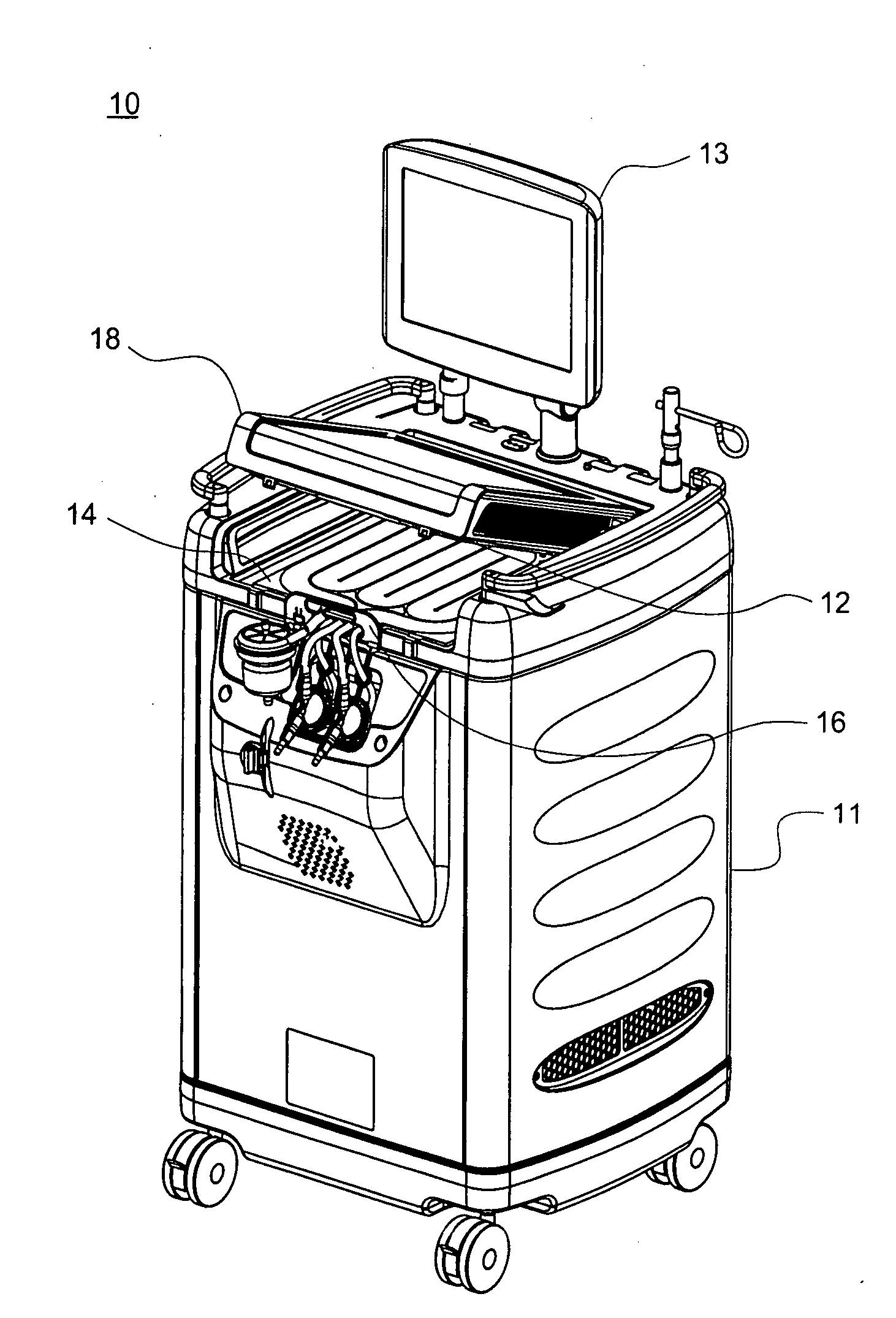
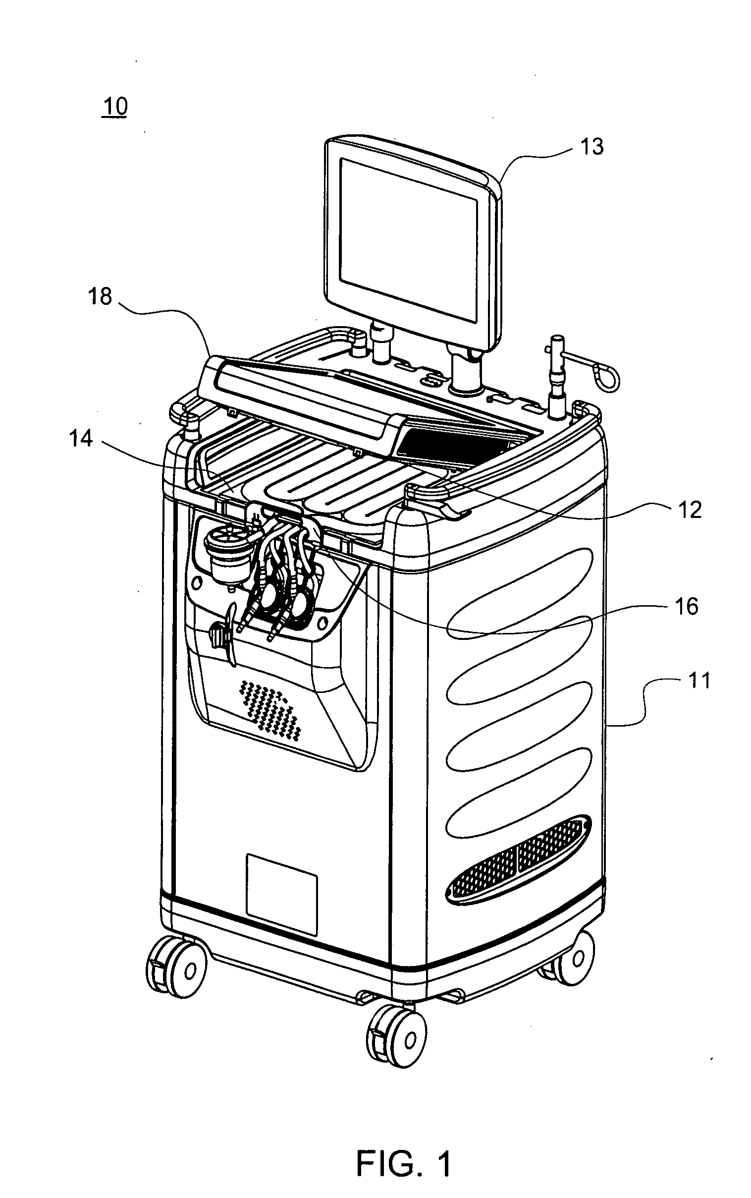
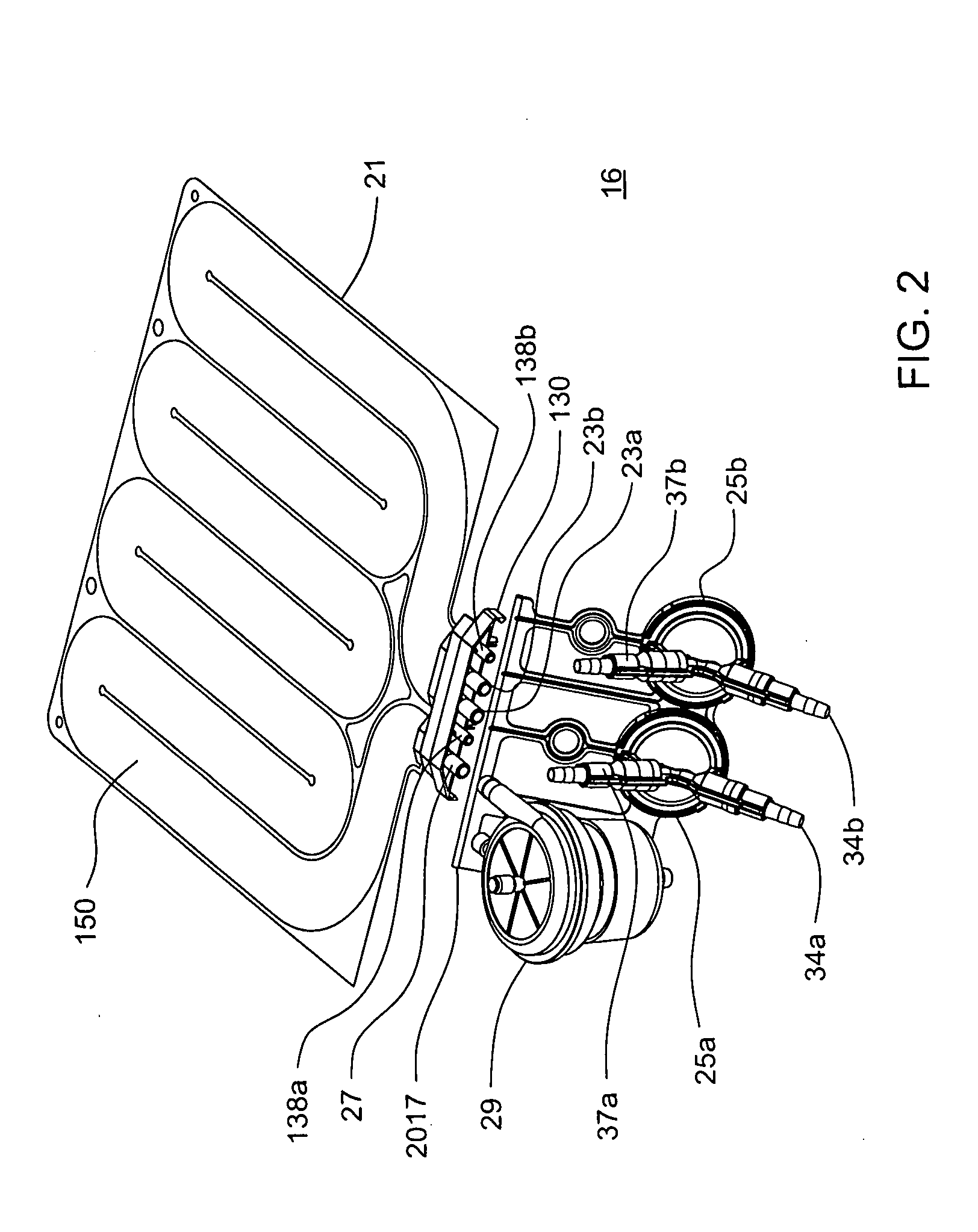
Image

Examples
Embodiment Construction
[0149]Definitions. As used in this description and the accompanying claims, the following terms shall have the meanings indicated, unless the context otherwise requires:
[0150]“Spheroid” means any three-dimensional shape that generally corresponds to a oval rotated about one of its principal axes, major or minor, and includes three-dimensional egg shapes, oblate and prolate spheroids, spheres, and substantially equivalent shapes.
[0151]“Hemispheroid” means any three-dimensional shape that generally corresponds to approximately half a spheroid.
[0152]“Spherical” means generally spherical.
[0153]“Hemispherical” means generally hemispherical.
[0154]“Dithering” a valve means rapidly opening and closing the valve.
[0155]“Pneumatic” means using air or other gas to move a flexible membrane or other member.
[0156]“Substantially tangential” means at an angle less than 75° to a tangent, or in the case of a flat wall, at an angle of less than 75° to the wall.
[0157]“Fluid” shall mean a substance, a li...
PUM
 Abstract
Description
Claims
Application Information