
Methods for determining the approximate location of a device from ambient signals

a technology of ambient signals and location information, applied in traffic control systems, wireless communication, instruments, etc., can solve the problems of limited computing information for users, research facilities or big businesses that could employ computing machines, and early machines with vastly less computing power, so as to reduce facilitate approximation, and reduce the effect of computational and data storage requirements

Inactive Publication Date: 2005-01-27
MICROSOFT TECH LICENSING LLC
View PDF55 Cites 77 Cited by
  • Summary
  • Abstract
  • Description
  • Claims
  • Application Information

AI Technical Summary

Benefits of technology

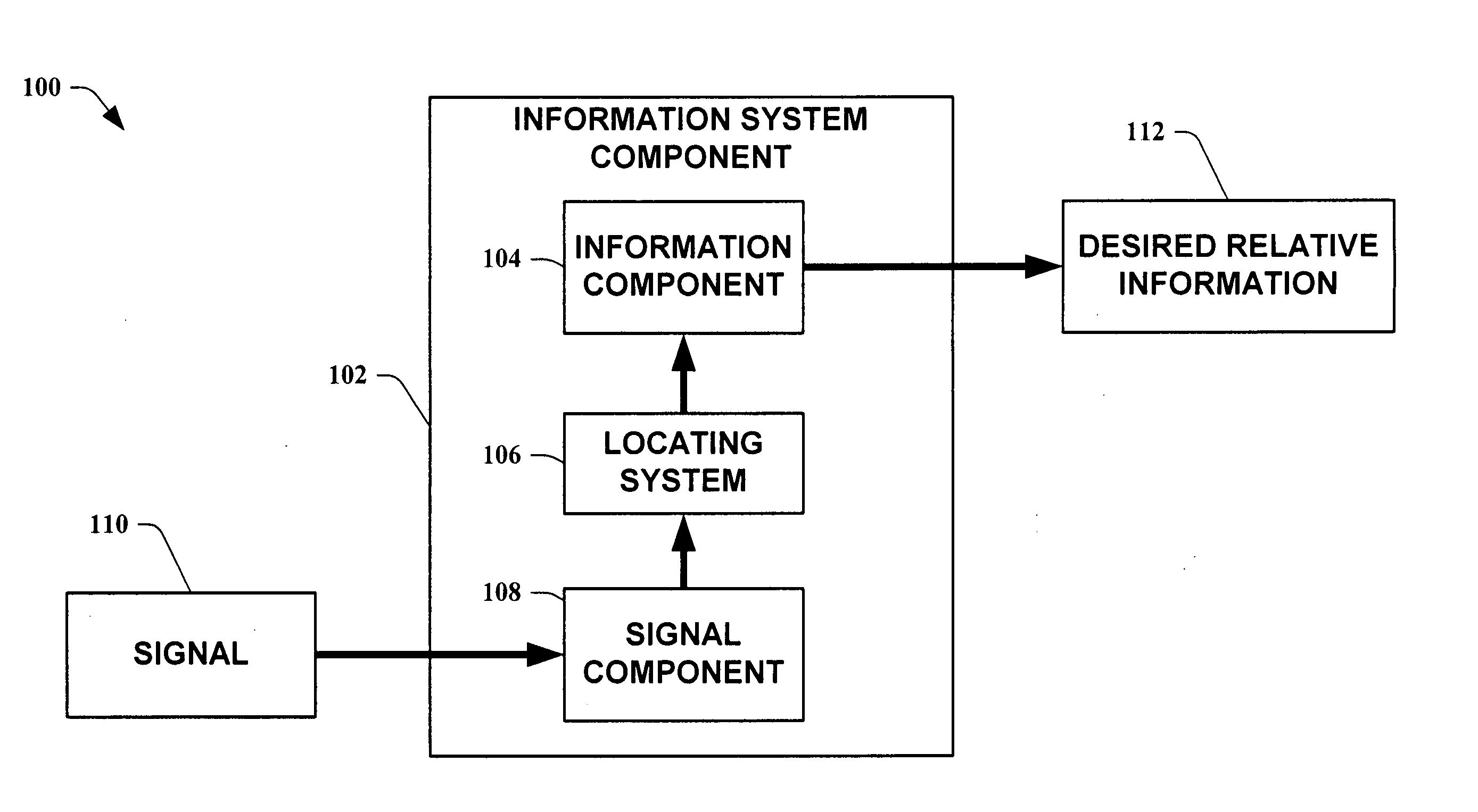
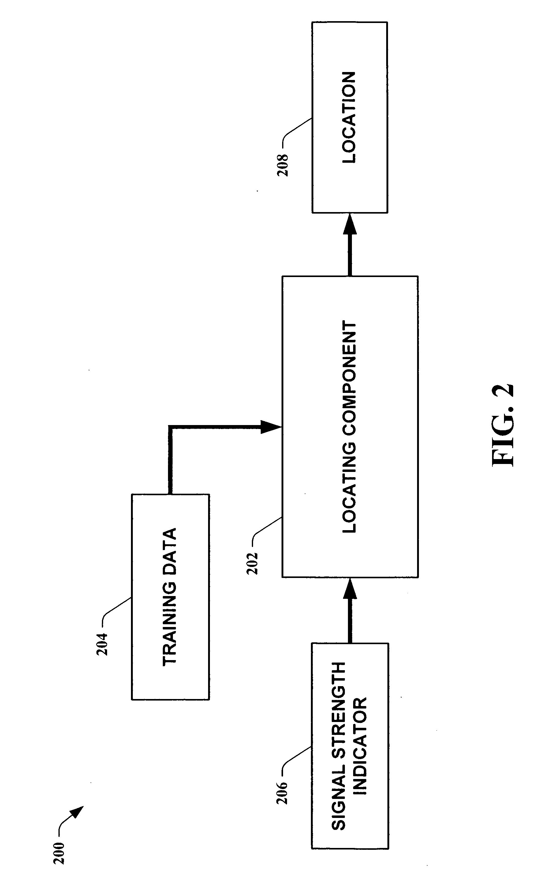
The present invention relates generally to location determination, and more particularly to methods for providing an approximate location of a device utilizing multiple ambient signals from emitting entities, such as, for example, base stations, towers, mobile platforms, building antennae, and the like. A monotonically increasing nature between actual signal strengths and signal strength indicators provided by technology, such as, for example, Microsoft's Smart Personal Object Technology (SPOT), is leveraged to determine a device location. This provides a locating means without a need for calibrating individual devices and / or requiring a defined measuring unit for determining location. By utilizing inferencing applied to observations of ambient signal frequencies, a means of locating a device is obtained. In one aspect of the present invention, a rank vector is utilized to insulate results from a monotonically increasing function of measured signal strength vectors. This desensitizes the present invention from needing to obtain absolute signal strengths in order to determine locations. The present invention also facilitates approximations for locating a device by providing a method that does not require obtaining a substantial number of available signals while still providing substantial accuracy in determining locations, reducing computational and data storage requirements.

Problems solved by technology

Despite their enormous size, the early machines had vastly less computing power than today's machines.
This meant that only large research facilities or big businesses could employ computing machines.
Generally speaking, however, a user was restricted to computing information available only on that computer.
This was great for local telephone calls, but enormously expensive for long distance calls.
This greatly limits their flexibility for a typical user who is always “on the go.” Technology has continued to respond by developing computers that require a device to be placed on the body along with large batteries and glasses that provide a viewing screen.
Although much more portable, the bulkiness of these devices limit their usefulness, and the reduction in device size (over a typical desktop computer) generally limits its computing power.
Additionally, because of its intricacies, it is a device that a user must choose to wear, knowing its limitations and restrictions and being careful not to damage the delicate equipment.
Even this has not been enough for some users who attempt to obtain the smallest and lightest computing devices that allow them access anywhere they can carry them.
However, this is time consuming and typically the programming is done assuming a user is stationary.
The first civilian devices that utilized satellite tracking were bulky and hard to use.
Unfortunately, lugging a laptop, hooking up all the connections to the GPS antennae, and finding power for all the equipment, made utilizing this technology burdensome.
Additionally, by the nature of its technology, GPS only works when it can directly access a minimum number of satellites, limiting its use in congested areas such as in larger cities with skyscrapers and especially when a person is indoors.

Method used


Image

  • Methods for determining the approximate location of a device from ambient signals
  • Methods for determining the approximate location of a device from ambient signals
  • Methods for determining the approximate location of a device from ambient signals

Examples


Embodiment Construction

The present invention is now described with reference to the drawings, wherein like reference numerals are used to refer to like elements throughout. In the following description, for purposes of explanation, numerous specific details are set forth in order to provide a thorough understanding of the present invention. It may be evident, however, that the present invention may be practiced without these specific details. In other instances, well-known structures and devices are shown in block diagram form in order to facilitate describing the present invention.

As used in this application, the term “component” is intended to refer to a computer-related entity, either hardware, a combination of hardware and software, software, or software in execution. For example, a component may be, but is not limited to being, a process running on a processor, a processor, an object, an executable, a thread of execution, a program, and / or a computer. By way of illustration, both an application ru...


PUM


Abstract

The present invention leverages changes in the sensed strength of radio signals at different locations to determine a device's location. In one instance of the invention, inference procedures are used to process ambient commercial radio signals, to estimate a location or a probability distribution over the locations of a device. In an instance of the invention, learning and inference methods are applied to rank vector of signal strength vectors. Moving to such rank orderings leads to methods that bypass consideration of absolute signal strengths in location calculations. The invention facilitates approximations for locating a device by providing a method that does not require a substantial number of available ambient signal strengths while still providing useful location inferences in determining locations.

Description

TECHNICAL FIELD The present invention relates generally to location determination, and more particularly to methods for providing an approximate location of a device utilizing ambient signal strengths. BACKGROUND OF THE INVENTION Computers were developed to aid people with repetitive tasks that were deemed to be extremely time consuming. Most of the early computers were used for complex mathematical problem solving. The first computing machines were extremely large compared to computers utilized today. Despite their enormous size, the early machines had vastly less computing power than today's machines. Generally speaking, the sizes of computing devices were driven by the sizes of the existing electronic components of that era. This meant that only large research facilities or big businesses could employ computing machines. As new technology allowed for smaller electronic devices to be developed, computing devices also diminished in size. Although still lacking in power by today's...

Claims


Application Information

Patent Timeline
IPC IPC(8): G01S5/00H04B7/26G01S19/09G01S19/46G08G1/0962G08G1/0967H04Q7/34
CPCG01S5/0027G01S5/0252G08G1/0962G08G1/096775G08G1/096716G08G1/096741G08G1/0967G01S5/0278
Inventor KRUMM, JOHN C.CERMAK, GERALD F.HORVITZ, ERIC J.MILLER, EDWARD C.YOUSSEF, ADEL AMIN ABDELAZIM
Owner MICROSOFT TECH LICENSING LLC
Learn More