Method and apparatus with a splittable hemostatic valve with a variable aperture

a hemostatic valve and variable aperture technology, applied in the field of endovascular devices, can solve the problems of too large friction between the valve and the floppy lead, difficult insertion of these types of leads through the hemostatic valve provided on the introducer, and inability to be easily manipulated, so as to reduce the diameter of the aperture

Inactive Publication Date: 2005-01-27
KURTH
View PDF5 Cites 57 Cited by
  • Summary
  • Abstract
  • Description
  • Claims
  • Application Information

AI Technical Summary

Benefits of technology

[0011] In one embodiment the means for varying the diameter of the aperture and/or compression of the valve member around the aperture comprises a compression collar disposed about the valve housing, which is compressed radially by the compression collar. The compression collar is substantially fixed in radius and is coupled to the housing. The housing ...

Problems solved by technology

This combination between thinness and pliability often makes the insertion of these types of leads through a hemostatic valve provided on an introducer difficult, if not impractical.
The problem becomes exacerba...

Method used


Image

  • Method and apparatus with a splittable hemostatic valve with a variable aperture
  • Method and apparatus with a splittable hemostatic valve with a variable aperture
  • Method and apparatus with a splittable hemostatic valve with a variable aperture

Examples


Embodiment Construction

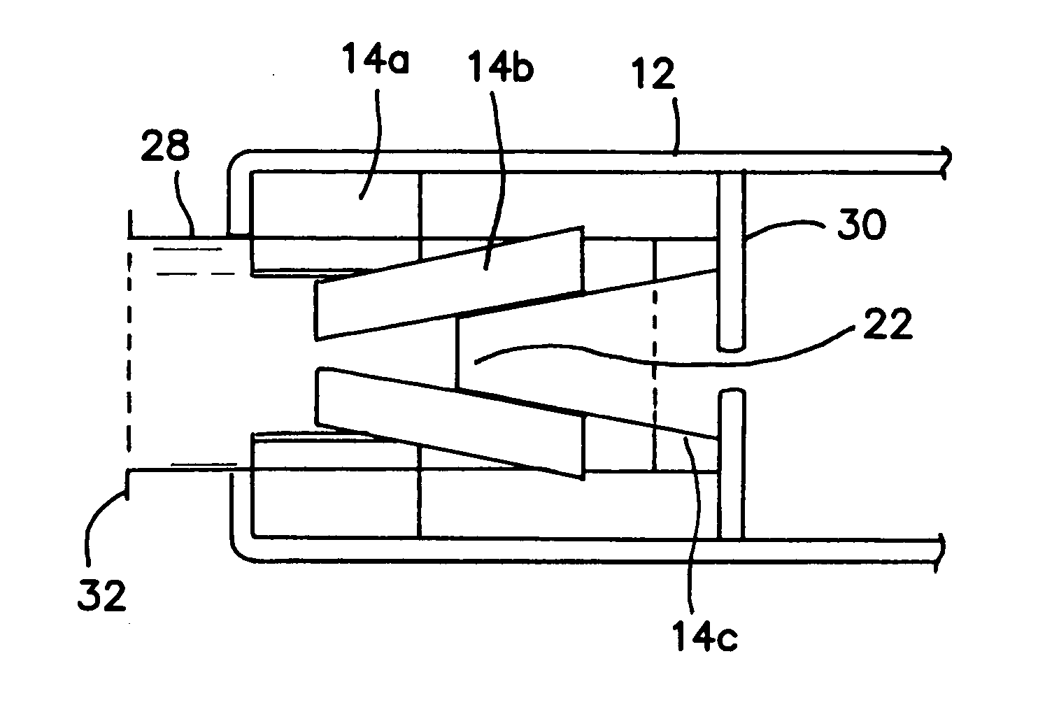
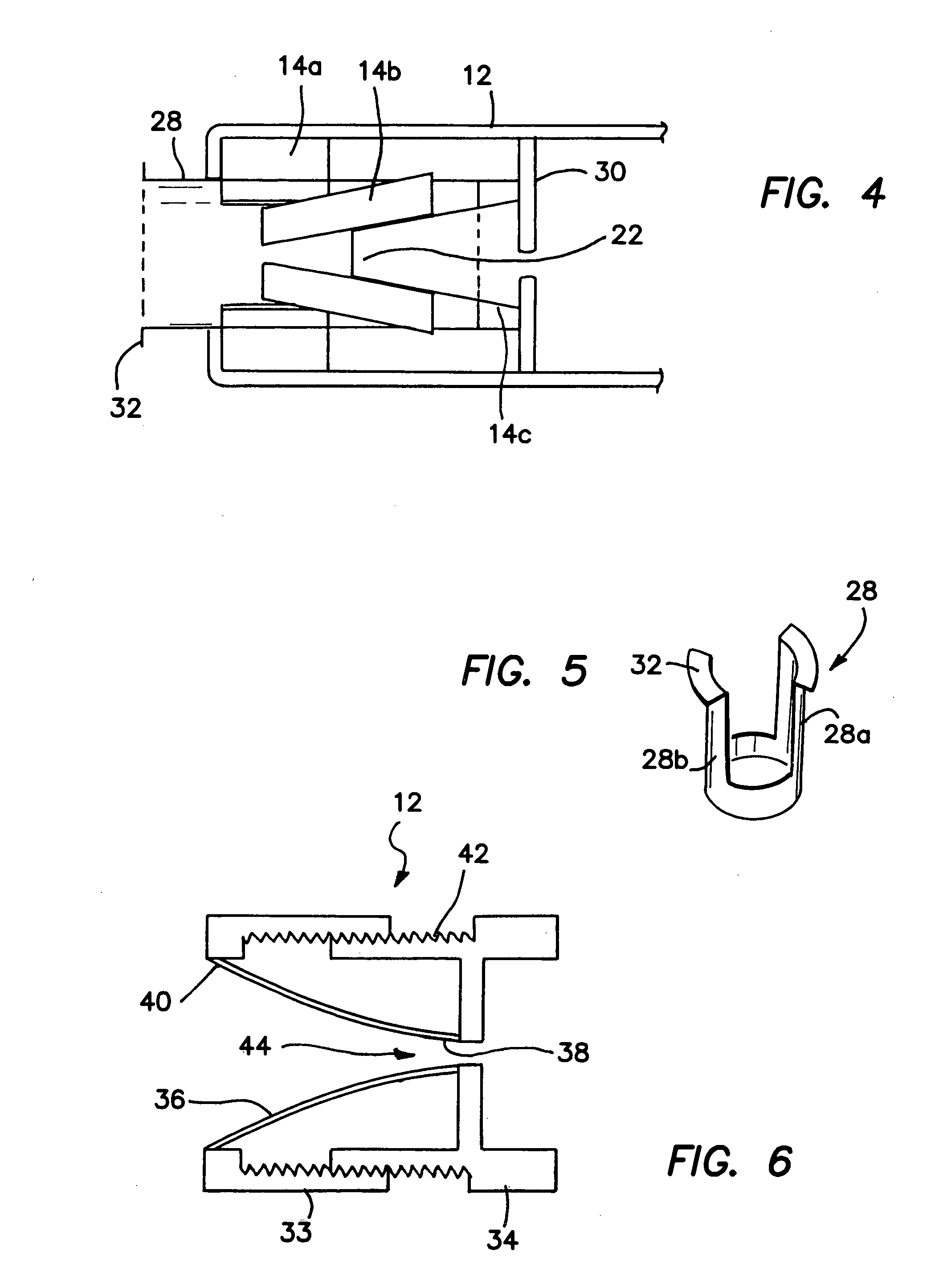
[0033] It must be borne in mind throughout the following disclosure that in each of the embodiments in FIGS. 1-5, valve housing 12 and / or its membrane or valve body 14 are openable, separable, tearable, sliceable, splittable or peelable by any one or more of a variety of means, such as described with respect to the separable valves disclosed below in the incorporated applications and patents.

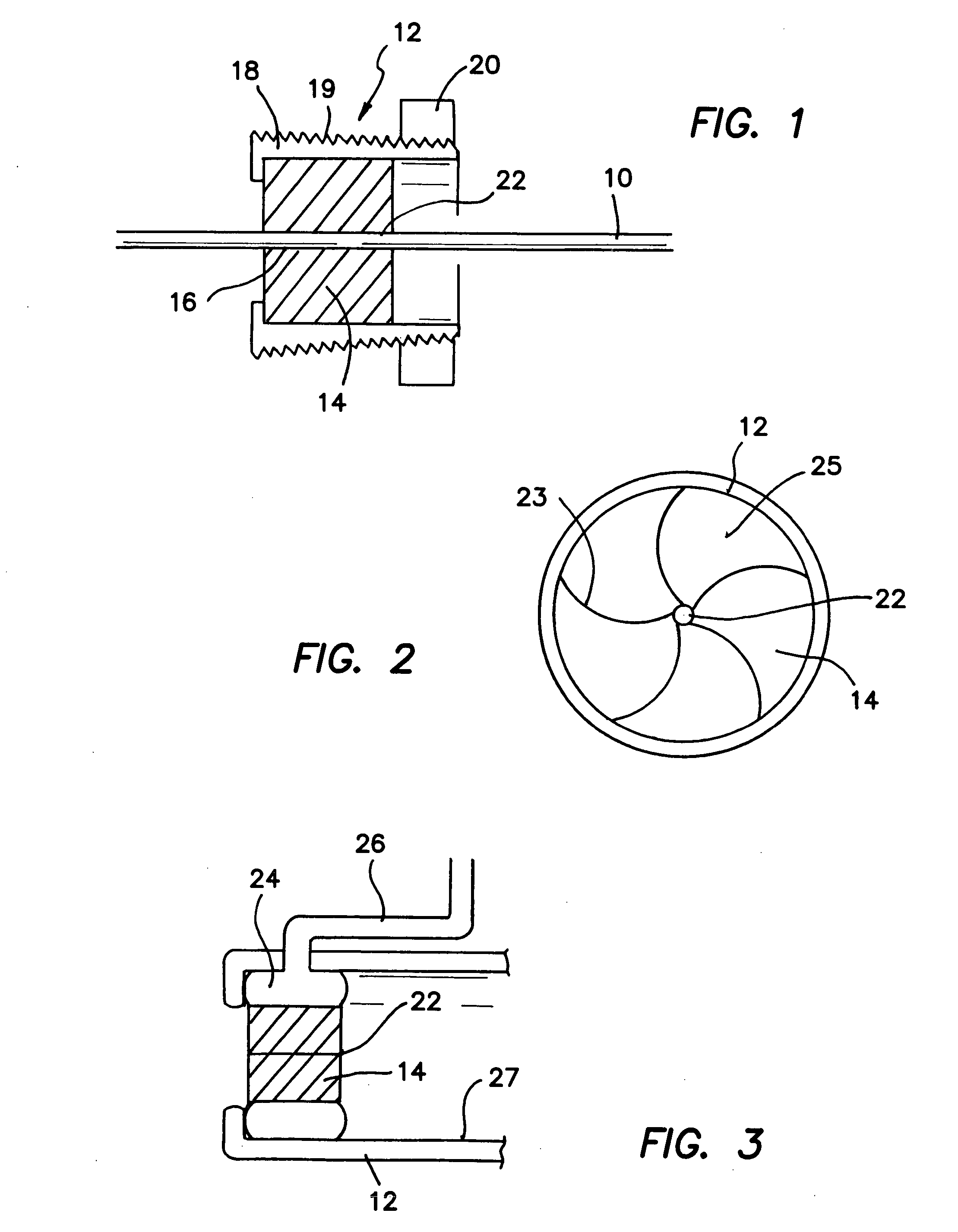
[0034] As shown in FIG. 1 in side cross-sectional view a hemostatic valve housing 12 encapsulates or contains an elastomeric valve 14 through which an elgongate instrument 10 is disposed through an aperture or slit 22 defined through elastomeric valve 14. Instrument 10 may be any kind of vascular instrument, such as a guidewire, a pacemaker lead, a catheter, an introducer, a dilator or any other vascular tool or implement.

[0035] The proximal end of housing 12 is made so that it is compressible, such as being made of connecting sectors or portions of wedge shaped walls 18 having an exterior thr...


PUM


Abstract

A separable hemostatic valve comprises a separable valve housing, a separable compressible valve in which an aperture is defined disposed in the valve housing, a means for varying the diameter of the aperture and/or compression of the valve around the aperture, and a means for separating the valve housing and valve into at least two parts. The means for varying the diameter of the aperture and/or compression of the valve comprises means for radially, laterally or longitudinally compressing the valve. The means for separating the valve housing and valve into at least two parts comprising means for slicing, splitting, peeling, tearing, parting or opening the valve housing and/or valve into parts.

Description

RELATED APPLICATIONS [0001] The present application is related to U.S. Provisional Patent Application, Ser. No. 60 / 479,531, filed on Jun. 18, 2003, which is incorporated herein by reference and to which priority is claimed pursuant to 35 USC 119.BACKGROUND OF THE INVENTION [0002] 1. Field of the Invention [0003] The invention relates to the field of endovascular devices and in particular to devices, such as introducers, which are combined with hemostatic valves. [0004] 2. Description of the Prior Art [0005] Pacemaker leads currently being implanted into the left ventricle and coronary sinus typically have a diameter of 4 to 5 F and are provided with floppy tips. This combination between thinness and pliability often makes the insertion of these types of leads through a hemostatic valve provided on an introducer difficult, if not impractical. The problem becomes exacerbated when more than one lead must be disposed through the same hemostatic valve. The friction between the valve and ...

Claims


Application Information

Patent Timeline
IPC IPC(8): A61MA61M5/178A61M39/06A61M39/22A61M39/28
CPCA61M39/0613A61M39/287A61M39/228
Inventor KURTH, PAUL A.
Owner KURTH
Why Eureka
Try Eureka