Compliant, porous, rolled stent

a stent and porous technology, applied in the field of biomedical devices, can solve the problems of large proportion of treated vessels restenosis, conventional mesh and tubular stents may be too rigid to easily negotiate tortuous vessels, and the end of restenosis of the stent may not be easily accessibl

Inactive Publication Date: 2005-01-27
MEDTRONIC VASCULAR INC
View PDF8 Cites 107 Cited by
  • Summary
  • Abstract
  • Description
  • Claims
  • Application Information

AI Technical Summary

Problems solved by technology

Soon after the procedure, however, a significant proportion of treated vessels restenose.
Conventional mesh and tubular stents may be too rigid to easily negotiate tortuous vessels and may straighten out the natural curves in a vessel when deployed.
In addition, tubular stents such as that disclosed in U.S. Pat. No. 6,533,905 to Johnson et al. offer no openings for endothelial growth through the stent, which may result in restenosis at the ends of the stents.
While mesh and helical wire stents permit endothelial growth, the minimal surface area of such stents may result in limited support for the wall of the vessel and may expose the bloodstream to plaque or other embolic material attached to the wall of the vessel.
In addition, mesh and helical wire stents may offer little surface area for adhering drug coatings and thus are limited in their ability to deliver drugs to the wall of a vessel.
The free ends of these stents may flare out when delivered, injuring the wall of the vessel, or may protrude into the blood flow, which is thought to promote thrombosis.
Because helical stents are generally wound tightly for delivery, the free ends may also whip around the catheter at high speed as they unwind, again injuring the wall of a vessel or possibly dislodging pieces of plaque that may result in embolization.
Helical stents may also experience considerable longitudinal shortening after they are fully unwound, possibly resulting in improper placement of the stent.
Localized slipping or migration of individual turns of a coil of a helical stent may also result in placement problems.
While this device addresses some of the problems described above, it does not entirely eliminate the disadvantages resulting from helical stents with free ends.
The free ends of the stent may still flare out when balloon expanded, while the minimal number of windings may limit the flexibility and compliance of the stent.
In addition, the turns of the stent are not linked or stabilized, allowing individual turns to slip or migrate and possibly allowing the stent to stretch, reducing its diameter.

Method used


Image

  • Compliant, porous, rolled stent
  • Compliant, porous, rolled stent
  • Compliant, porous, rolled stent

Examples


Embodiment Construction

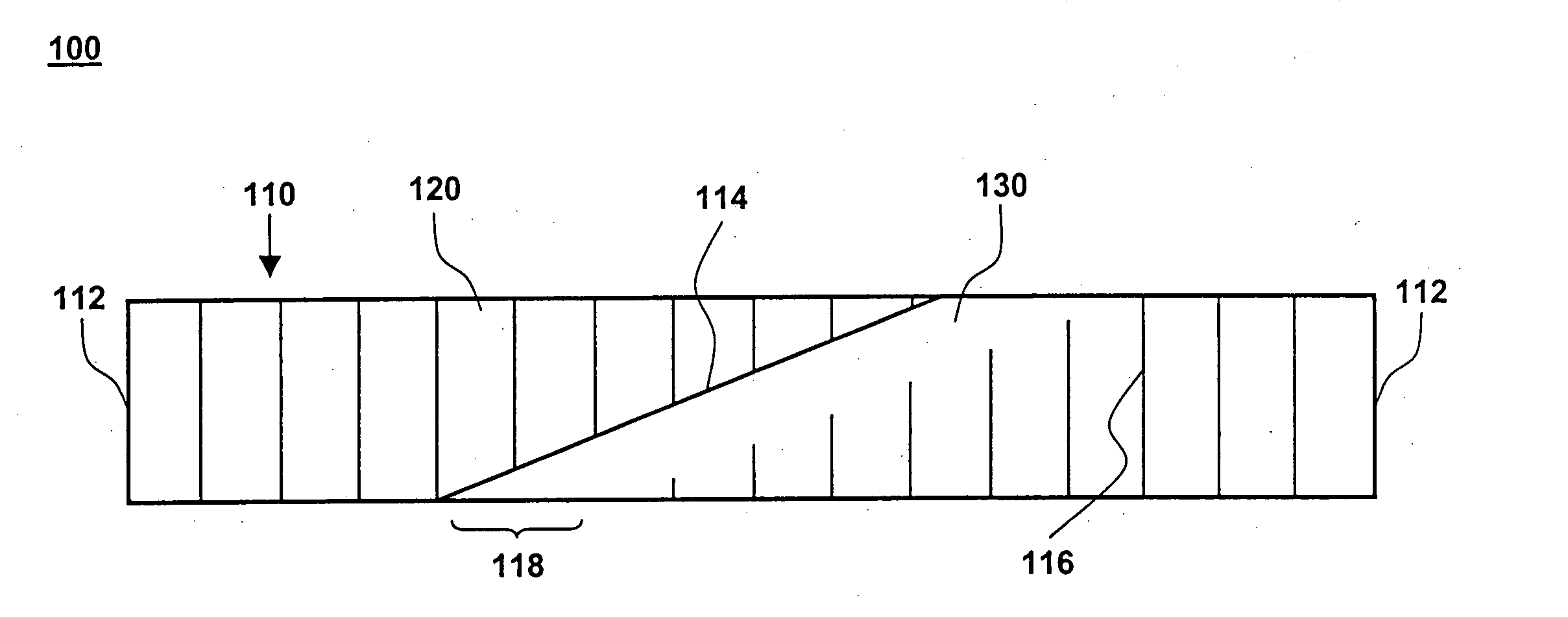
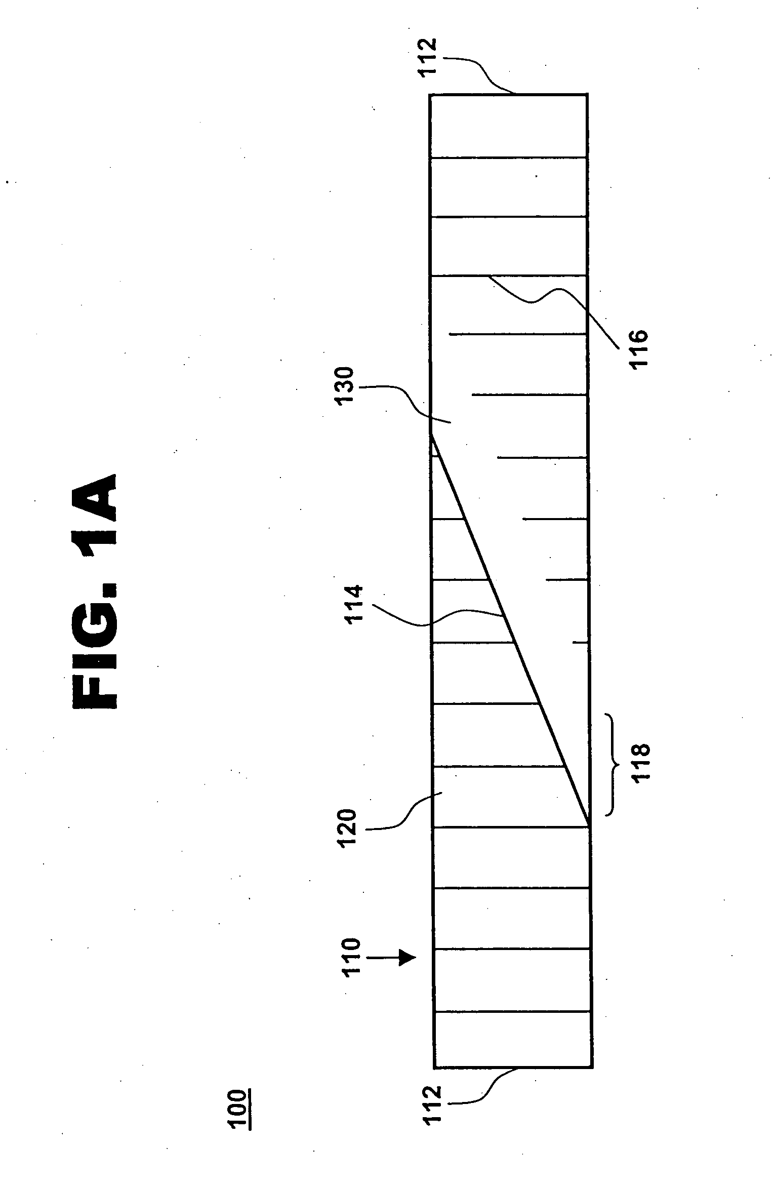
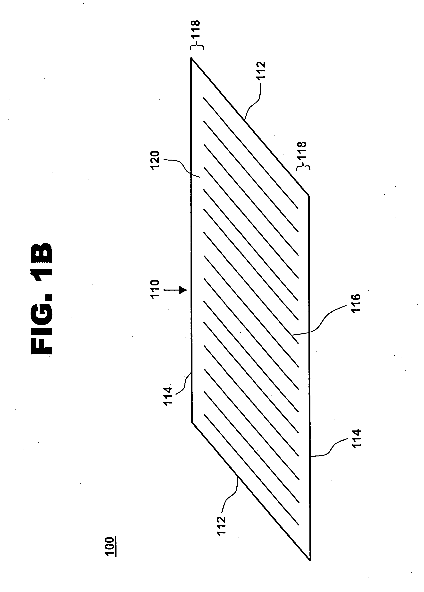
[0018] One aspect of the present invention is a compliant, porous, rolled stent. One embodiment of the stent, in accordance with the present invention, is illustrated in FIGS. 1A and 1B at 100. A completed stent is shown in FIG. 1A, while the same stent is shown reduced in size and in a preliminary, unrolled configuration in FIG. 1B. Stent 100 includes a stent framework 110 and a therapeutic coating 120. Stent framework 110 has two short sides 112 and two long sides 114 and includes a plurality of slits 116 formed parallel to short sides 112. Edge portions 118 adjacent to long sides 114 are unslit and form a spiral backbone 130 in the rolled stent. Short sides 112 form the proximal and distal ends of stent 100.

[0019] Stent framework 110 may be made of a wide variety of medical implantable materials, such as a shape-memory material, a biocompatible material, a biodegradable material, a metal, a ceramic, a polymer, and combinations thereof. For example, the framework may comprise a s...


PUM


Abstract

The invention provides a compliant, porous, rolled stent, comprising a stent framework configured as a rhomboid having two short sides and two long sides. The stent framework includes a plurality of slits formed parallel to the short sides of the rhomboid, edge portions adjacent to the long sides of the rhomboid being unslit. The stent framework is rolled at an angle such that the long sides of the rhomboid overlap one another to form a tubular structure. The tubular structure has a spiral backbone formed by the unslit edge portions adjacent to the long sides of the rhomboid. The short sides of the rhomboid form the proximal and distal ends of the stent.

Description

RELATED APPLICATIONS [0001] This application claims the benefit of U.S. Provisional Patent Application 60 / 489,682 filed Jul. 24, 2003.TECHNICAL FIELD [0002] This invention relates generally to biomedical devices that are used for treating vascular conditions. More specifically, the invention relates to a compliant, porous, rolled stent. BACKGROUND OF THE INVENTION [0003] Stents are generally cylindrical-shaped devices that are radially expandable to hold open a segment of a vessel or other anatomical lumen after implantation into the body lumen. Various types of stents are in use, including expandable and self-expanding stents. Expandable stents generally are conveyed to the area to be treated on balloon catheters or other expandable devices. For insertion, the stent is positioned in a compressed configuration along the delivery device, for example crimped onto a balloon that is folded or otherwise wrapped about a guide wire lumen that is part of the delivery device. After the stent...

Claims


Application Information

Patent Timeline
Patent Type & Authority Applications(United States)
IPC IPC(8): A61F2/00A61F2/92
CPCA61F2250/0067A61F2/92
Inventor NAKAHAMA, JAMES E.CAMPBELL, TODD D.
Owner MEDTRONIC VASCULAR INC
Why Eureka
Try Eureka