Turbine rotor and method for producing the rotor

a technology of rotor and rotor plate, which is applied in the direction of liquid fuel engines, vessel construction, marine propulsion, etc., can solve the problems of insufficient strength of riveted joints, severe damage to turbines, and inability to be used in practice, etc., and achieves low cost, easy and reliable rotor, and simple use

Inactive Publication Date: 2009-05-07
MAN TURBO AG
View PDF8 Cites 8 Cited by
  • Summary
  • Abstract
  • Description
  • Claims
  • Application Information

AI Technical Summary

Benefits of technology

[0022]The blades can be twisted easily and reliably upon assembly. The force needed to twist the shroud plates is generated positively and directly on the shroud plates and also positively maintained on the shroud plates during installation. The application of the invention is thus independent of the friction generated between the contact surfaces of the blades in the rotor.
[0023]After the installation of each blade, its radial position in the rotor can be checked. The gap for instal

Problems solved by technology

Vibrations in the blades of steam or gas turbines lead to the formation of cracks in the blades, and after enough time a blade can break off, causing severe damage to the turbine.
In the case of turbines with high circumferential velocities, the strength of these riveted joints is insufficient.
The known design suffers from the following weaknesses, however.
Because of the manufacturing tolerances to which each blade is subject and which are different in each case, it is impossible in practice—in the case of a stage with 70 rotor blades, for example—to install the blades in such a way that there is no play between them.
Because the base surface and the shroud plate surface of each blade form a wedge, the outward-shifting movements of the blades just described

Method used


Image

  • Turbine rotor and method for producing the rotor
  • Turbine rotor and method for producing the rotor
  • Turbine rotor and method for producing the rotor

Examples


Embodiment Construction

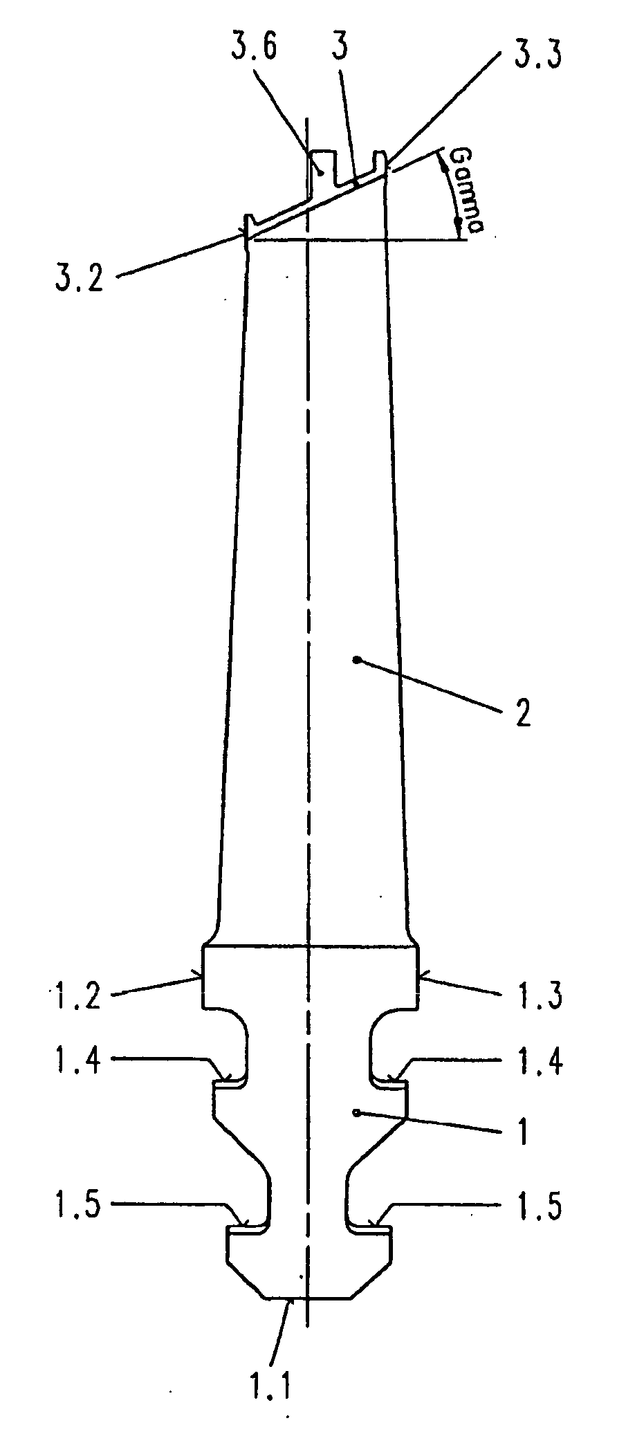
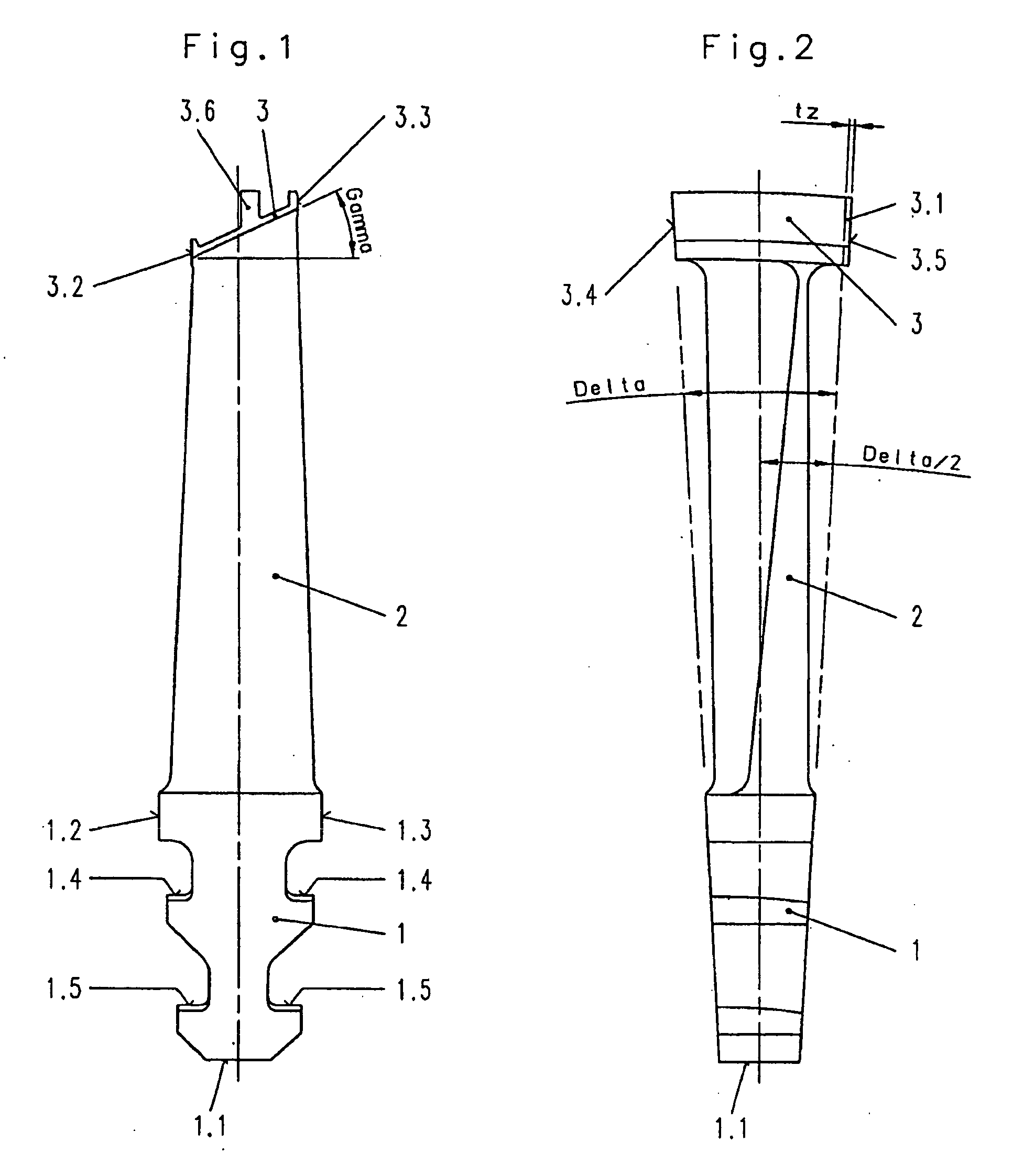
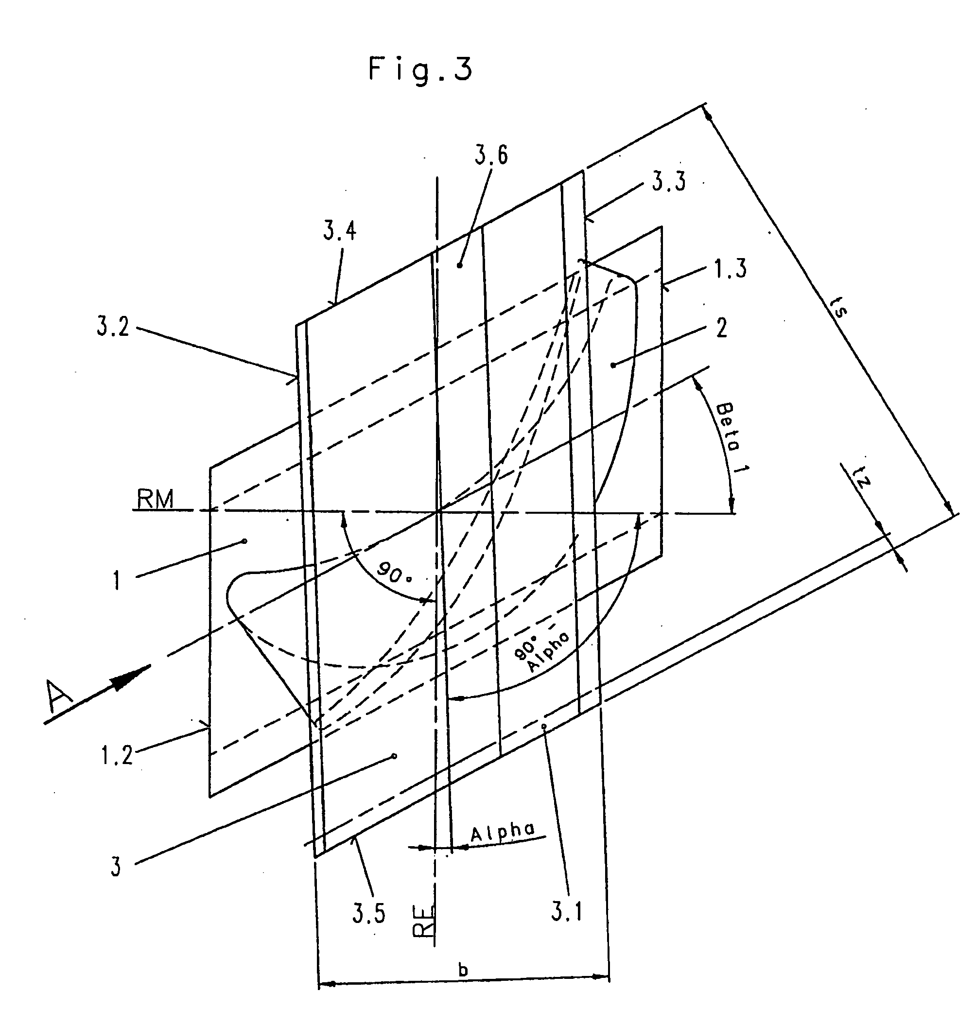
[0039]The blade of a turbine consists of a blade foot 1, which has a tapered shape and, in the case shown here, is designed as a double hammer head with support shoulders 1.4 and 1.5, lateral surfaces 1.2 and 1.3, and a base surface 1.1. From the foot plate of the blade, a blade profile 2 proceeds upward with a taper and also with a twist. A shroud plate 3 with an expansion bevel, which forms an angle Gamma with the horizontal (FIG. 1), is provided at the top end of the blade profile 2. The blade foot 1 and the shroud plate 3 have the geometric form of a rhomboid or parallelogram. The shroud plate 3 has two side or plan surfaces 3.2, 3.3 and two end or spacing surfaces 3.4 and 3.5. The plate is also provided with a sealing comb 3.6. In the installed state, the side or plan surfaces 3.2, 3.3 are aligned with each other in the circumferential direction of the rotor 4, whereas the end or spacing surfaces 3.4, 3.5 are at an angle to the longitudinal axis of the rotor 4 (rotor center RM)...


PUM

PropertyMeasurementUnit
Angleaaaaaaaaaa

Abstract

A turbine rotor has a row of turbine blades associated with a circumferential groove in a disk, each turbine blade having foot received in the groove, a blade profile above the foot, and a shroud plate above the profile. Each blade foot and each shroud plate have end surfaces and side surfaces which form a rhomboid, the end surfaces of each shroud plate tapering toward each other along respective radii and abutting the end surfaces of adjacent shroud plates to form a closed ring. The blade profiles are torsionally stressed by applying a force to each plate in a direction parallel to the axis of the disk, thereby twisting the cover plates through an angle alpha so that the side surfaces of adjacent cover plates are circumferentially aligned in a plane perpendicular to the longitudinal axis. This force is maintained by clamping devices applied to the combs of adjacent blades.

Description

CROSS REFERENCE TO RELATED APPLICATION[0001]This application is a Continuation-in-Part of PCT Application No. PCT / EP2006 / 006218 filed 27 Jun. 2006, which claims priority from DE 10 2005 030 516.4 filed 28 Jun. 2005.FIELD OF THE INVENTION[0002]The invention pertains to a turbine rotor and to a method for producing a rotor of the type having a row of turbine blades associated with each groove in a rotor disk, wherein each turbine blade has a blade foot received in the groove, a blade profile above the foot, and a shroud plate above the profile, each blade foot and each shroud plate having end surfaces and side surfaces which form a rhomboid, the end surfaces of each shroud plate tapering toward each other along respective radii and abutting the end surfaces of adjacent shroud plates so that the shroud plates form a closed ring.DESCRIPTION OF THE RELATED ART[0003]Vibrations in the blades of steam or gas turbines lead to the formation of cracks in the blades, and after enough time a bla...

Claims


Application Information

Patent Timeline
IPC IPC(8): F01D5/30F01D5/22B23P15/04
CPCF01D5/225F01D5/24Y10T29/49316F05D2230/64F01D5/3038
Inventor BROCK, HANS-EGON
Owner MAN TURBO AG
Why Eureka
Try Eureka