Automatic focus adjusting mechanism and optical image acquisition apparatus

a technology of automatic focus adjustment and optical image acquisition, which is applied in the direction of camera focusing arrangement, printers, instruments, etc., can solve the problems of focus adjustment error, complex optical system, and increased system cos

Inactive Publication Date: 2010-09-30
NEC CORP +1
View PDF6 Cites 8 Cited by
  • Summary
  • Abstract
  • Description
  • Claims
  • Application Information

AI Technical Summary

Problems solved by technology

However, this scheme requires a light source for generating a focusing laser beam, in addition to a light source for picking up pattern images, which inevitably makes the optical system complex.
Further, in accordance with increases in the degree of complexity of the optical system, the cost of the system will inevitably be increased.
If a light source of a wavelength longer than that of the pattern pickup light source is used to suppress the cost, the difference in wavelength may lead to a focus adjustment error.
As a result, a focus error can be detected with high accuracy.
However, in this method, it is possible that the slit image projected on the test sample (mask surface) will be subjected to diffraction effect due to a mask pattern formed on the test sample, whereby the light amount distribution on the focus adjusting aperture plane will be scattered to make it difficult to detect the focus.
This problem will be conspicuous if a very fine pattern is formed on the test sample, since the very fine pattern causes serious diffraction effect.
Further, if the light amount distribution at the edge of the aperture formed in the focus adjusting aperture stop is reduced, correct focus error detection cannot be realized.
These problems will be caused by diffraction effect of a pattern formed on the surface of a test sample.
Since test samples have different patterns, changes in light amount due to diffraction cannot be estimated beforehand.

Method used


Image

  • Automatic focus adjusting mechanism and optical image acquisition apparatus
  • Automatic focus adjusting mechanism and optical image acquisition apparatus
  • Automatic focus adjusting mechanism and optical image acquisition apparatus

Examples


first embodiment

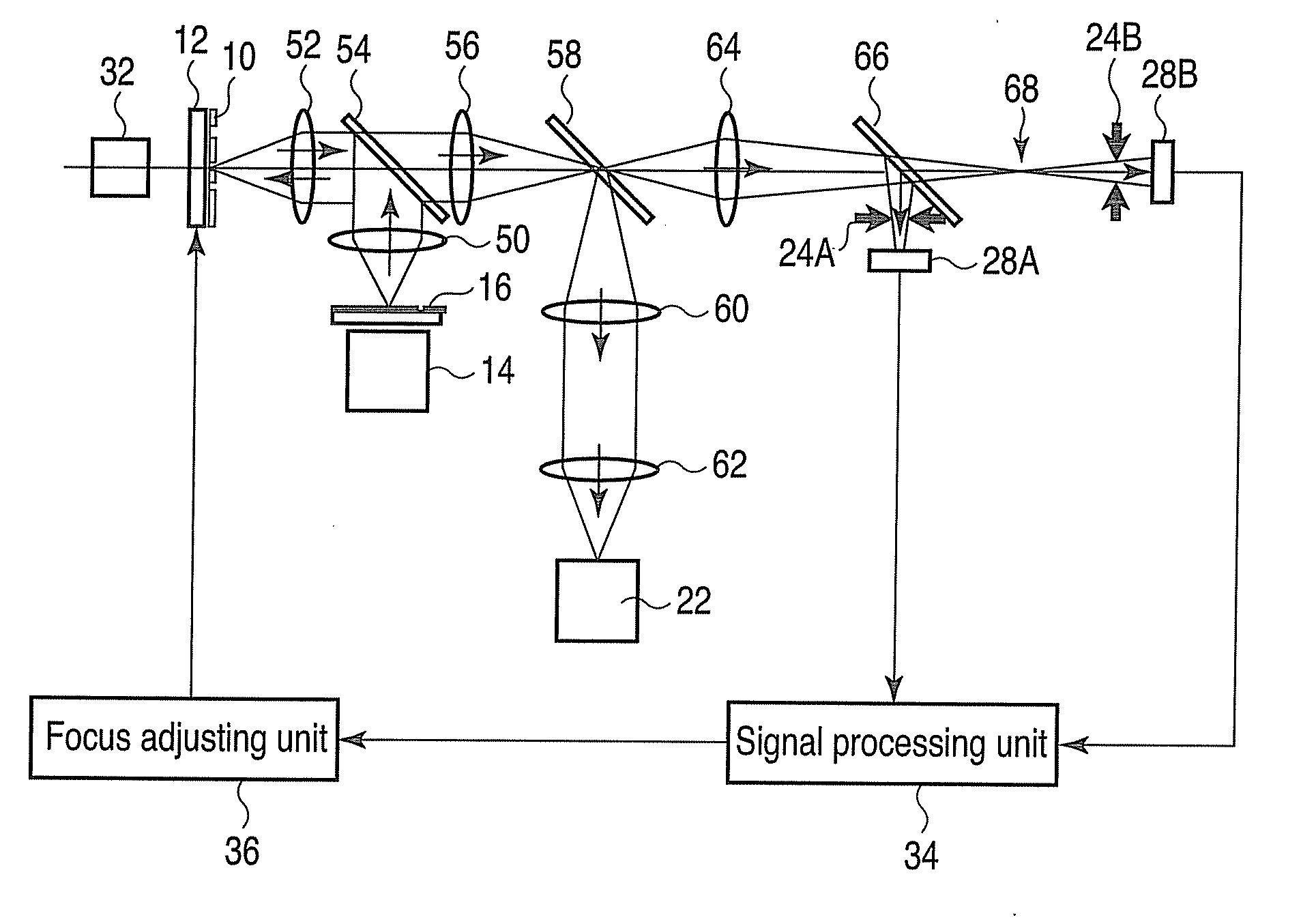
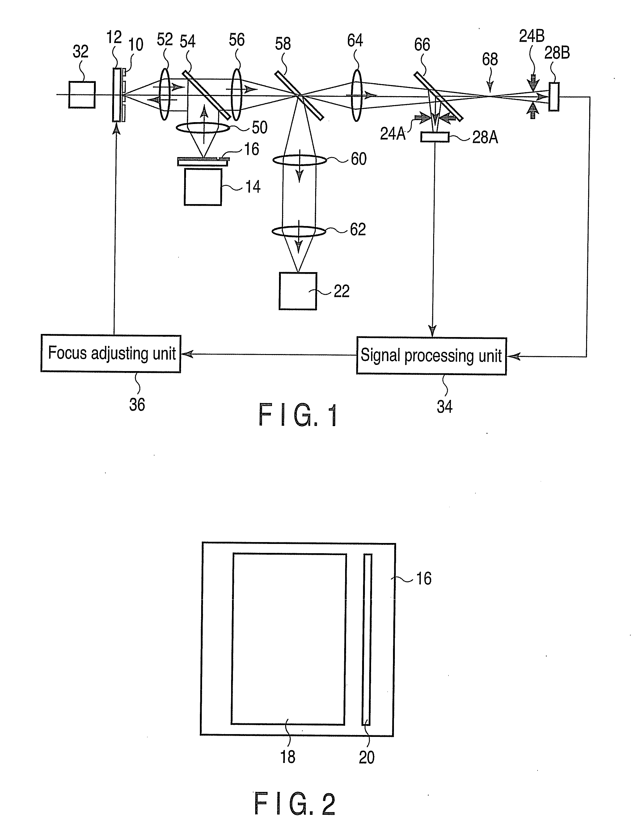
[0038]FIG. 1 is a schematic view illustrating an optical image acquisition apparatus with an automatic focus adjusting mechanism, according to a first embodiment of the invention. As shown in FIG. 1, in the optical image acquisition apparatus, a test sample 10, such as a mask (or photomask), is placed on a mount table 12. An image of a pattern on the test sample 10 is picked up by an optical image receiving unit 22. An automatic focus adjusting mechanism incorporated in the optical image acquisition apparatus causes an object lens 52 to focus on the surface of the test sample 10, i.e., adjusts the position of the mount table 12, with the test sample 10 mounted thereon, along the optical axis so that the distance between the test sample 10 and the object lens can be kept constant in the focused state. As will be described later, in the automatic focus adjusting mechanism, an observation light beam emitted from a reflection observing light source 14 is reflected by the surface of the ...

second embodiment

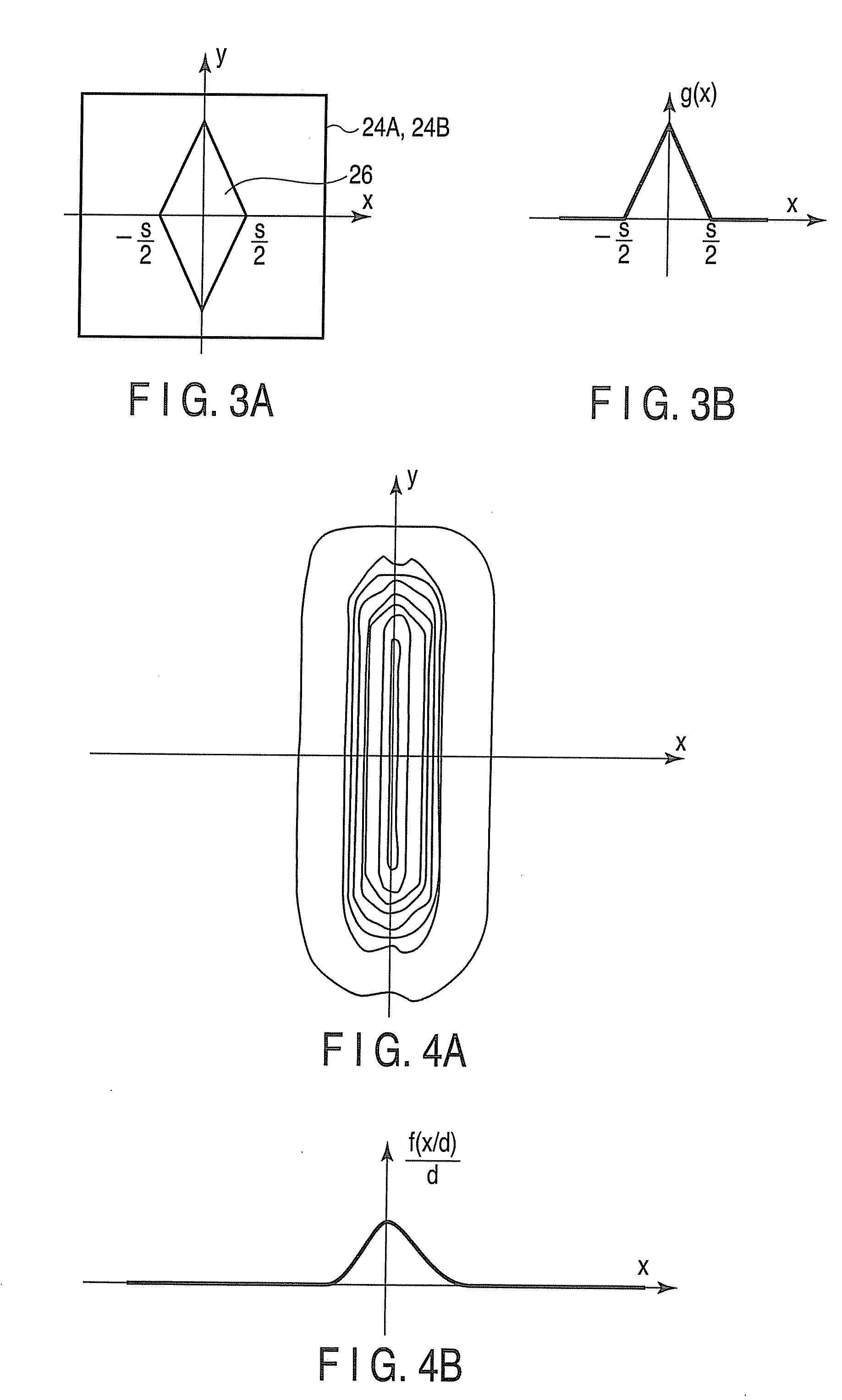
[0075]An optical image acquisition apparatus incorporating an automatic focus adjusting mechanism according to a second embodiment has substantially the same structure as the first embodiment shown as in FIG. 1. In the second embodiment, the apertures 26 of focus adjusting aperture stops 24A and 24B each have linear and curved edges as shown in FIG. 15A. Each of the curved edges of the aperture 26 is defined by a curve obtained by compressing a log function horizontally and / or vertically as shown in FIG. 5B. Part of the boundary defining the aperture 26, which is indicated by the broken line in FIG. 15A, is defined by the curve indicated by the broken line in FIG. 15B.

[0076]On each focus adjusting aperture plane, the center of the aperture 26 is set as the origin, the axis along the width of the aperture 26 is set as the x axis, and the axis along the length of the aperture 26 is set as the y axis. The length of the imaginary line segment at position x, which is defined in the apert...


PUM

PropertyMeasurementUnit
optical imageaaaaaaaaaa
aperture lengthaaaaaaaaaa
widthaaaaaaaaaa

Abstract

In an automatic focus adjusting mechanism, a test sample having a patterned surface is mounted on a mount table, and an light beam passing through a slit formed in a field stop is applied to the patterned surface of the test sample. The light beam reflected from the test sample is split into two segment light beams. Focus adjusting aperture stops having respective apertures formed rhomboid are provided across the optical paths of the segment light beams. The amounts of the segment light beams passing through the rhomboid apertures are detected by light receiving units. Based on the difference between the detected light amounts, the position of the mount table is controlled by the focus adjusting unit.

Description

CROSS-REFERENCE TO RELATED APPLICATIONS[0001]This application is based upon and claims the benefit of priority from prior Japanese Patent Application No. 2009-076753, filed Mar. 26, 2009, the entire contents of which are incorporated herein by reference.BACKGROUND OF THE INVENTION[0002]1. Field of the Invention[0003]The present invention relates to an automatic focus adjusting mechanism for focus adjustment, and to an optical image acquisition apparatus with the automatic focus adjusting mechanism, which is used to acquire an optical image of a pattern formed on a test sample such as a mask.[0004]2. Description of the Related Art[0005]In optical apparatuses, such as lithography apparatuses for transferring a circuit pattern to a semiconductor substrate, and defect testing apparatuses for testing a semiconductor integrated circuit pattern, it is necessary to acquire an optical image with high resolution equal to or less than the circuit pattern size. To acquire an optical image with ...

Claims


Application Information

Patent Timeline
Patent Type & Authority Applications(United States)
IPC IPC(8): G03B13/00G01N21/956G03F1/84H01L21/027H01L21/66
CPCG03B13/00
Inventor SHIRATSUCHI, MASATAKAHONGUH, YOSHINORIHIRONO, MASATOSHIOGAWA, RIKISUGIHARA, SHINJI
Owner NEC CORP
Why Eureka
Try Eureka