Method of controlling the welding of a three-dimensional structure

a three-dimensional structure and control method technology, applied in the direction of programmed manipulators, vessel construction, auxiliaries for welding, etc., can solve the problems of serious problems in technical realization and expense, the dimensional accuracy of the piece and its positioning accuracy have not reached a sufficiently high level, and the welding of shaped pieces has not been practicable in the practical production. , to achieve the effect of eliminating the disadvantages of the known method, simple and as easily possibl

Active Publication Date: 2005-01-27
MEYER TURKU
View PDF9 Cites 44 Cited by
  • Summary
  • Abstract
  • Description
  • Claims
  • Application Information

AI Technical Summary

Benefits of technology

[0005] An aim of the present invention is to provide a novel method, as simple and as easily feasible as possible, of welding a three-dimensional structure by using a welding robot or the like, where the disadvantages related to the known method have been eliminated.

Problems solved by technology

Especially in shipbuilding robotized welding of shaped pieces has not been possible in practical production on one hand due to programming problems and on the other hand due to the accuracy of manufacture.
In practice, the dimensional accuracy of the piece and its positioning accuracy have not reached a sufficiently high level that the robotizing could be based for instance on information obtained from the design system.
Then, however, serious problems have been encountered both in the technical realization and in expense.
This method is advantageous in itself, but it is not as such applicable to the welding of three-dimensional curved pieces.
The method is laborious and its image processing is complicated, and therefore the method is quite time-consuming.
Inaccuracies related to the practical welding process cannot be avoided by using this method.

Method used


Image

  • Method of controlling the welding of a three-dimensional structure
  • Method of controlling the welding of a three-dimensional structure
  • Method of controlling the welding of a three-dimensional structure

Examples


Embodiment Construction

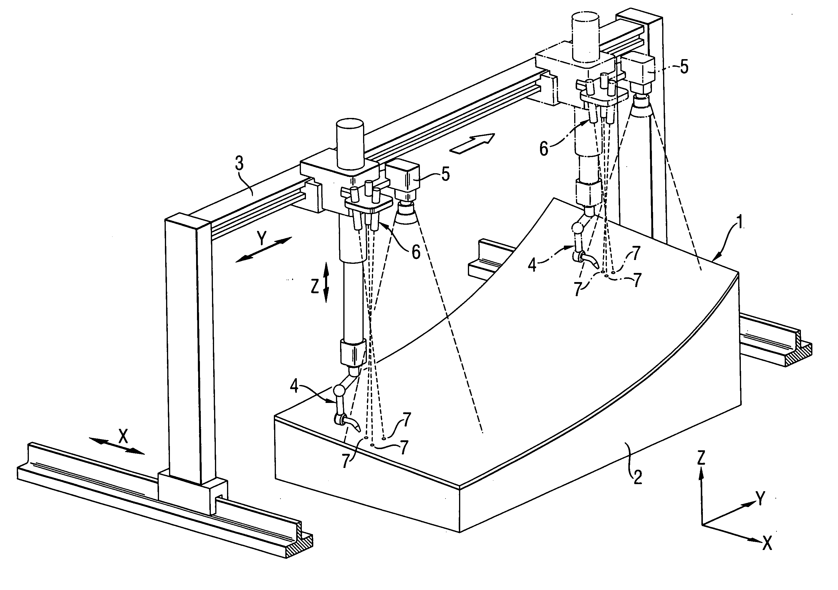
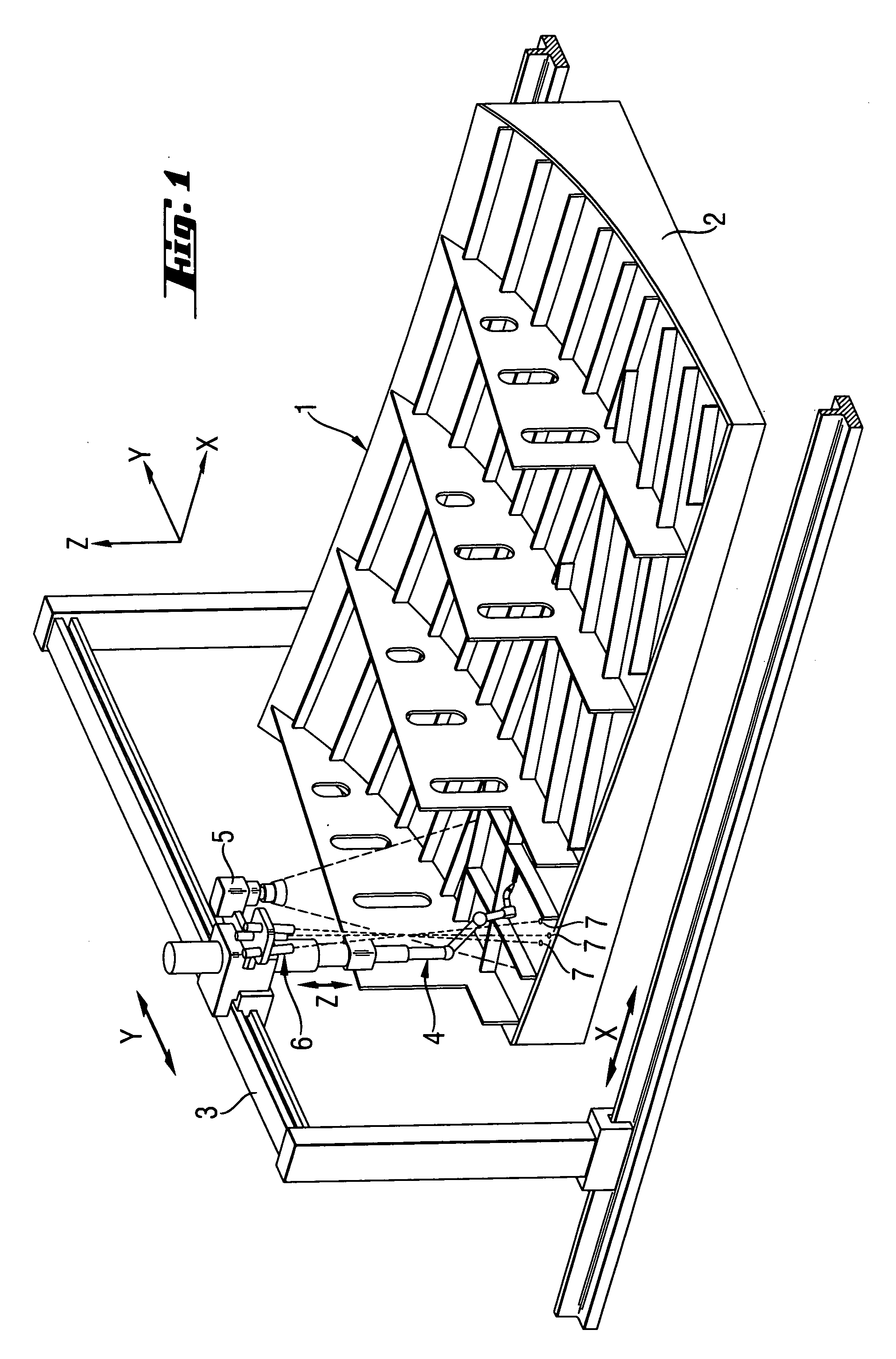
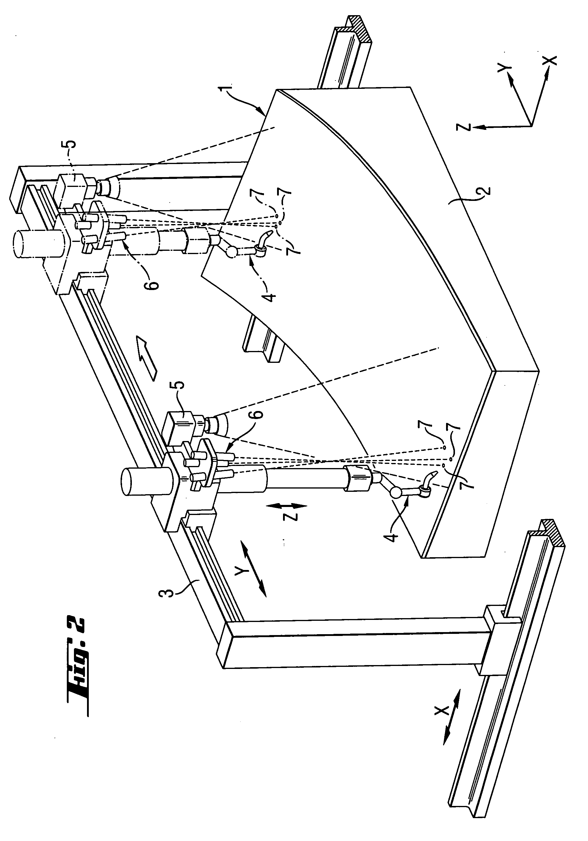
[0015] In the figures the reference numeral 1 indicates a structure to be welded, which in this case is a shaped piece used in shipbuilding and has a plurality of both longitudinal and transverse support structures, an essential part of which can be welded by means of a controllable robot. The shaped piece is curved about one axis and it may be curved about two axes. The shaped piece 1 is placed on a support base 2, which is located within the working area of a robot portal 3. A welding robot 4 is located at the robot portal 3 and in addition, the system comprises a camera device 5. The welding robot 4 is movable in the Y-direction and in the Z-direction relative to the robot portal. The robot portal 3 is in practice arranged on a rail track and is thus movable in the X-direction with respect to the working area. There may, if required, be several robot portals on the same rail track and each portal may have one or more welding robots 4. The welding robots 4 are movable within the w...


PUM

PropertyMeasurementUnit
structureaaaaaaaaaa
distanceaaaaaaaaaa
heightaaaaaaaaaa

Abstract

A welded structure is formed by arranging multiple pieces on a three-dimensional support base to provide an assembly in accordance with the structure to be welded and making a picture map of the assembly by photographing the assembly. Weld points are identified from the picture map and welding parameters are determined from the picture map. Control data specifying the weld points and welding parameters are supplied to welding equipment that is operable in a three-dimensional X-Y-Z coordinate system. The welding equipment is moved in the X-Y plane on the basis of the picture map and said control data. The welding equipment is moved along the Z-axis on the basis of Z-axis position data that are acquired by repeatedly measuring the Z-axis position of the support base.

Description

BACKGROUND OF THE INVENTION [0001] This invention relates to a method of controlling the welding in a three-dimensional X-Y-Z coordinate system. [0002] Especially in shipbuilding robotized welding of shaped pieces has not been possible in practical production on one hand due to programming problems and on the other hand due to the accuracy of manufacture. In practice, the dimensional accuracy of the piece and its positioning accuracy have not reached a sufficiently high level that the robotizing could be based for instance on information obtained from the design system. Efforts have been made to solve the problems by specifying the manufacture of components and the positioning accuracy and by developing programming systems based e.g. on simulation. Then, however, serious problems have been encountered both in the technical realization and in expense. [0003] U.S. patent application Ser. No. 09 / 941,485 discloses a method of flat welding pieces by utilizing a welding robot and an artif...

Claims


Application Information

Patent Timeline
Patent Type & Authority Applications(United States)
IPC IPC(8): B23K9/00B23K9/025B23K9/032B23K9/095B23K9/127B23K26/03B23K37/02B23K37/04B25J9/16B63B9/06G05B19/19
CPCB23K9/0026G05B2219/49362B23K9/032B23K9/1274B23K26/03B23K26/032B23K37/0235B23K37/0426B23K37/0461B23K2201/24B25J9/1697B63B9/06G05B2219/37555G05B2219/37571G05B2219/45104B23K9/0256B23K2101/24B63B73/43B63B73/60B23K37/02
Inventor GUSTAFSSON, JUKKAVEIKKOLAINEN, MIKKO
Owner MEYER TURKU
Why Eureka
Try Eureka