Heat sealing element and control of same

a technology of heat sealing element and controller, which is applied in the direction of transportation and packaging, packaging, other domestic articles, etc., can solve the problems of limited success in hermetically sealing the evacuated bags, high manufacturing cost of conventional commercial appliances and some consumer appliances, and complex construction and/or cumbersome operation. , to achieve the effect of minimizing waste of bag material

Inactive Publication Date: 2005-02-03
TILIA INT INC
View PDF62 Cites 51 Cited by
  • Summary
  • Abstract
  • Description
  • Claims
  • Application Information

AI Technical Summary

Benefits of technology

[0009] The present invention sets forth several embodiments relating to the position and control of heat sealing elements within a vacuum packaging appliance. The appliance comprises a lid adapted to define a vacuum chamber when it is moved to a closed position relative to a trough in the base of the device. A heat sealing element is mounted in close proximity to the trough. In another embodiment, the heat sealing element is mounted on the lid of the device and comes into contact with the vacuum bag when the lid is in a closed position. The placement of the heat sealing element adjacent to the trough minimizes wasted bag material as the heat seal is placed closer to the end of the bag itself.
[0010] In addition to the positioning of the heat sealing elements, the present invention also includes the controlling of these heat sealing elements. These embodiments provide features such as a heat sealing controller that allows an operator to select a type of heat seal formed on the evacuated container. The heat sealing controller controls the electrical current supplied to the heat sealing element as selected using a control panel that allows the operator to select between 3 types of heat seals. The control panel is operatively connected to the heat sealing element controller. The heat sealing element controller may also suspend heat sealing operations for a predetermined period of time in order to avoid heat seal element overheating. The controller also can adjust the duration of control signals applied to the heat sealing elements based on parameters such as the real-time temperature of the elements and the amount of liquid sensed in the trough while evacuating the container.
[0012] In the embodiments disclosed, the input used to control the heat sealing element may be any one or a combination of inputs such as temperature, type of heat seal selected by an operator, and amount of liquid sensed in a trough. In another embodiment, the heat seal element controller may increase or decrease the current provided to the heat sealing elements to maintain a constant element temperature or maintain the element within a predetermined temperature range. This type of feedback control allows for precise temperature control. In still another embodiment, the controller may send a signal to direct the vacuum pump exhaust under the heat sealing elements in order to cool the elements if the sealing elements have exceeded a predetermined temperature.

Problems solved by technology

Conventional commercial appliances and some consumer appliances are generally expensive to manufacture, complex in construction and / or cumbersome to operate.
There are also different types of heat sealing mechanisms contained in these prior art devices that have limited success in hermetically sealing the evacuated bags.
Although adaptable for low-volume home use, this type of system is cumbersome to use and normally requires a liquid separator or filter to prevent liquids or powders, retained within the bag, from being drawn into a vacuum pump connected to the nozzle.
This greatly adds to the cost and complexity of the device itself
This complex process in conjunction with the heat sealing mechanism is not reliable.
One problem with the above appliances is that there is a substantial amount of wasted vacuum bag material between the end of the bag and the heat seal as shown in Prior Art FIG. 12. FIG. 12 shows a container 20, with heat seals 21 and 22.
Therefore prior art devices waste approximately 30% of the vacuum bag material per use.
Another problem with prior art vacuum packaging appliances is that the temperature of the heat sealing mechanism is not accurately controlled.
Under the heat seal control mechanism of the prior art, sealing multiple bags without allowing the heat sealing element to cool results in bags beginning to seal before the vacuum process is complete.
This causes ineffective seals and prevents complete evacuation of gas from the bags, that results in expensive packaging bag waste.
Further, activating the elements without considering real-time temperature may cause damage to the appliance due to element overheating.

Method used


Image

  • Heat sealing element and control of same
  • Heat sealing element and control of same
  • Heat sealing element and control of same

Examples


Embodiment Construction

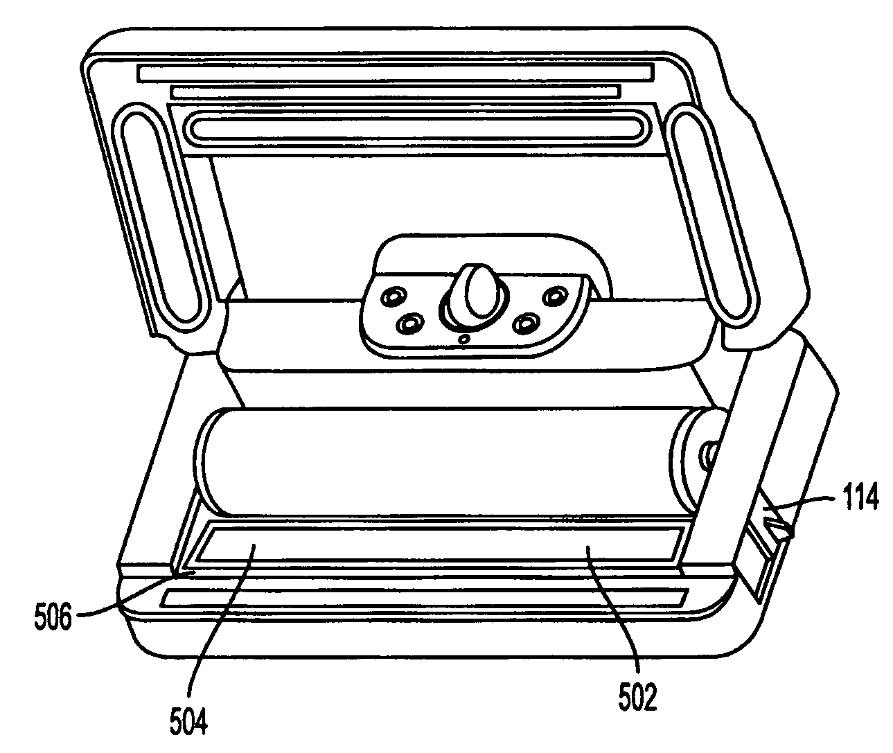
[0036] The present invention sets forth several embodiments relating to the position and control of heat sealing elements within a vacuum packaging appliance. The heat sealing element may be mounted on the lid or the base of the appliance. The placement of the heat sealing element within the appliance minimizes wasted bag material, as the heat seal is placed closer to the end of the bag itself The present invention also includes a heat sealing controller that may adjust the amount of current applied to the heat sealing element based on a number of different inputs. It will be understood by those skilled in the art that the description of the methods and structures of the vacuum packaging appliance described below is not intended to be limiting in anyway.

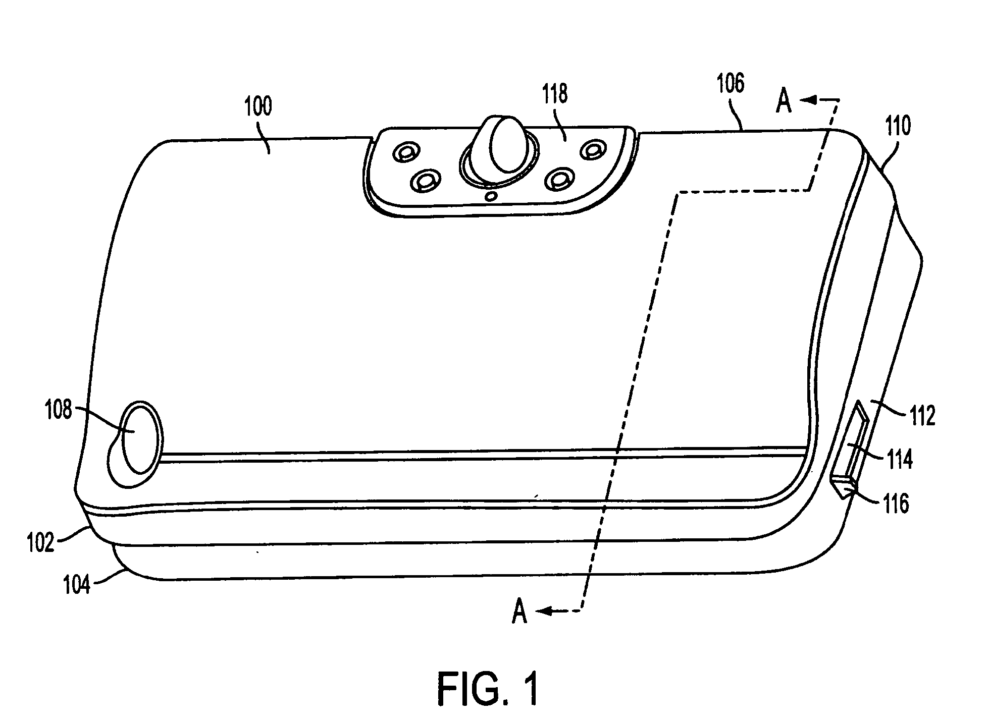
[0037]FIG. 1 shows a vacuum packaging appliance 100 for vacuum packaging articles in a container. The vacuum packaging appliance 100 has a lid 102 and a base 104 that are pivotally connected at a back side 106 of the appliance 100. ...


PUM

PropertyMeasurementUnit
lengthaaaaaaaaaa
wait timeaaaaaaaaaa
wait timeaaaaaaaaaa

Abstract

A vacuum packaging appliance for heat sealing items in a vacuum packaging plastic bag is disclosed. The appliance comprises a lid adapted to define a vacuum chamber when it is moved to a closed position relative to a trough in the base of the device. Adjacent to a trough in the lower portion of the device, a heat sealing element is placed in order to seal the contents of the bag once the vacuum packaging is complete. In another embodiment, the heat sealing element is mounted on the lid of the device and comes into contact with the vacuum bag when the lid is in a closed position. The heat sealing elements are controlled by a controller that allows operator selections of seals and sealing time adjustments based on inputs from a plurality of sensors. The controller is further able to energize one or two of the heating elements based on predetermined conditions. The methods and structures described control both heating and cooling of the heat sealing elements. The vacuum pump exhaust may also be directed below the heat sealing elements in order to cool the elements. The control and placement of the heat sealing elements allows for precise feedback and temperature control of the elements and therefore ensuring proper vacuum sealing of the containers.

Description

[0001] This application claims priority to Albritton et al.'s provisional patent application 60 / 491,876, filed Jul. 31, 2003, entitled HEAT SEALING ELEMENT AND CONTROL OF SAME, the contents of which are incorporated herein by reference.TECHNICAL FIELD [0002] The invention relates to a vacuum packaging appliance for packaging products and more particularly to heat sealing elements and a heat sealing controller used to seal an evacuated container once it has been processed by the vacuum packaging appliance. BACKGROUND OF THE INVENTION [0003] Presently, various appliances and methods are used for the purpose of vacuum sealing plastic bags and containers to protect perishables, such as foodstuffs, and other products against oxidation. Conventional commercial appliances and some consumer appliances are generally expensive to manufacture, complex in construction and / or cumbersome to operate. There are also different types of heat sealing mechanisms contained in these prior art devices tha...

Claims


Application Information

Patent Timeline
Patent Type & Authority Applications(United States)
IPC IPC(8): B65B31/02B65B51/14
CPCB65B51/146B65B31/046B29C65/223B29C65/30B29C66/1122B29C66/43121B29C66/81457B29C66/81811B29C66/8324B29C66/849B29C66/91231B29C66/91421B29C66/961B29C66/8221B29L2031/7128B29C66/00145B29C66/232B29C66/7352
Inventor ALBRITTON, CHARLES WADEHIGER, LANDEN
Owner TILIA INT INC
Why Eureka
Try Eureka