
Engine system with a thermal storage device, and engine temperature raising method

a technology of thermal storage and engine, which is applied in the direction of engine starters, electric control, machines/engines, etc., can solve the problems of deterioration of driveability and exhaust characteristics of the entire engine system, and achieve the effect of positive effects

Inactive Publication Date: 2005-02-03
TOYOTA JIDOSHA KK
View PDF9 Cites 42 Cited by
  • Summary
  • Abstract
  • Description
  • Claims
  • Application Information

AI Technical Summary

Benefits of technology

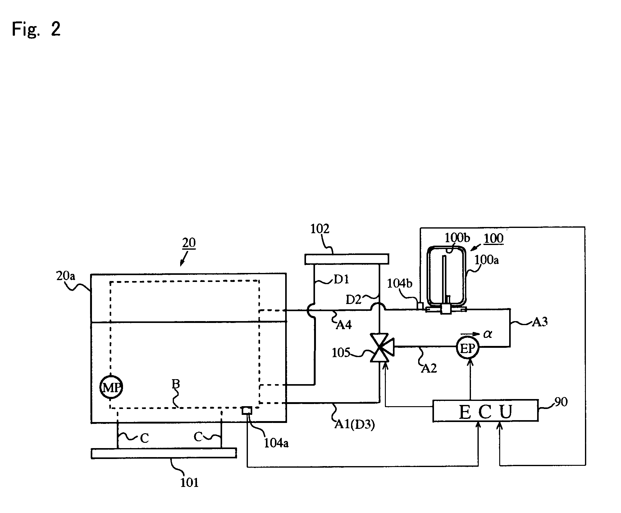
[0011] According to this arrangement, by setting the target value of the temperature of the internal combustion engine such that the lower the temperature of the internal combustion engine at the time of the heat supply, the smaller does the target value become, it is possible to prevent positive effects of the hot water supply, such as one represented by facilitated vaporization of the fuel supplied to the internal combustion engine, from being substantially reduced by negative effects of the hot water supply, such as one represented by an increase in the power consumption of an electric pump. In addition, the heat supply is stopped before the progress of a nonuniform temperature distribution in the interior of the internal combustion engine in accordance with the hot water supply (i.e., before a variation in the temperature distribution becomes greater than a certain extent). As a result, trouble resulting from the variation in the temperature distribution in the interior of the internal combustion engine can be eliminated. Thus, for example, it is possible to suppress reduction in the stability of the combustion state of the engine combustion state, especially a variation in combustion states caused between a plurality of cylinders in a multi-cylinder internal combustion engine.
[0024] According to an engine system of the present invention, it is possible to obtain positive effects due to the supply of heat from a heat storage device to an internal combustion engine, such as for example one represented by the facilitation of vaporization of the fuel supplied to the internal combustion engine.

Problems solved by technology

Such a temperature variation generated between the plurality of intake ports invites a variation in the combustion states between the plurality of cylinders, thus giving rise to a fear that the driveability and exhaust characteristics of the entire engine system might be deteriorated.

Method used


Image

  • Engine system with a thermal storage device, and engine temperature raising method
  • Engine system with a thermal storage device, and engine temperature raising method
  • Engine system with a thermal storage device, and engine temperature raising method

Examples


Embodiment Construction

[0035] Hereinafter, reference will be made to a preferred embodiment of the present invention in which the present invention is applied to a vehicle-mounted hybrid engine system.

[0036] [Basic Construction of the Engine System]

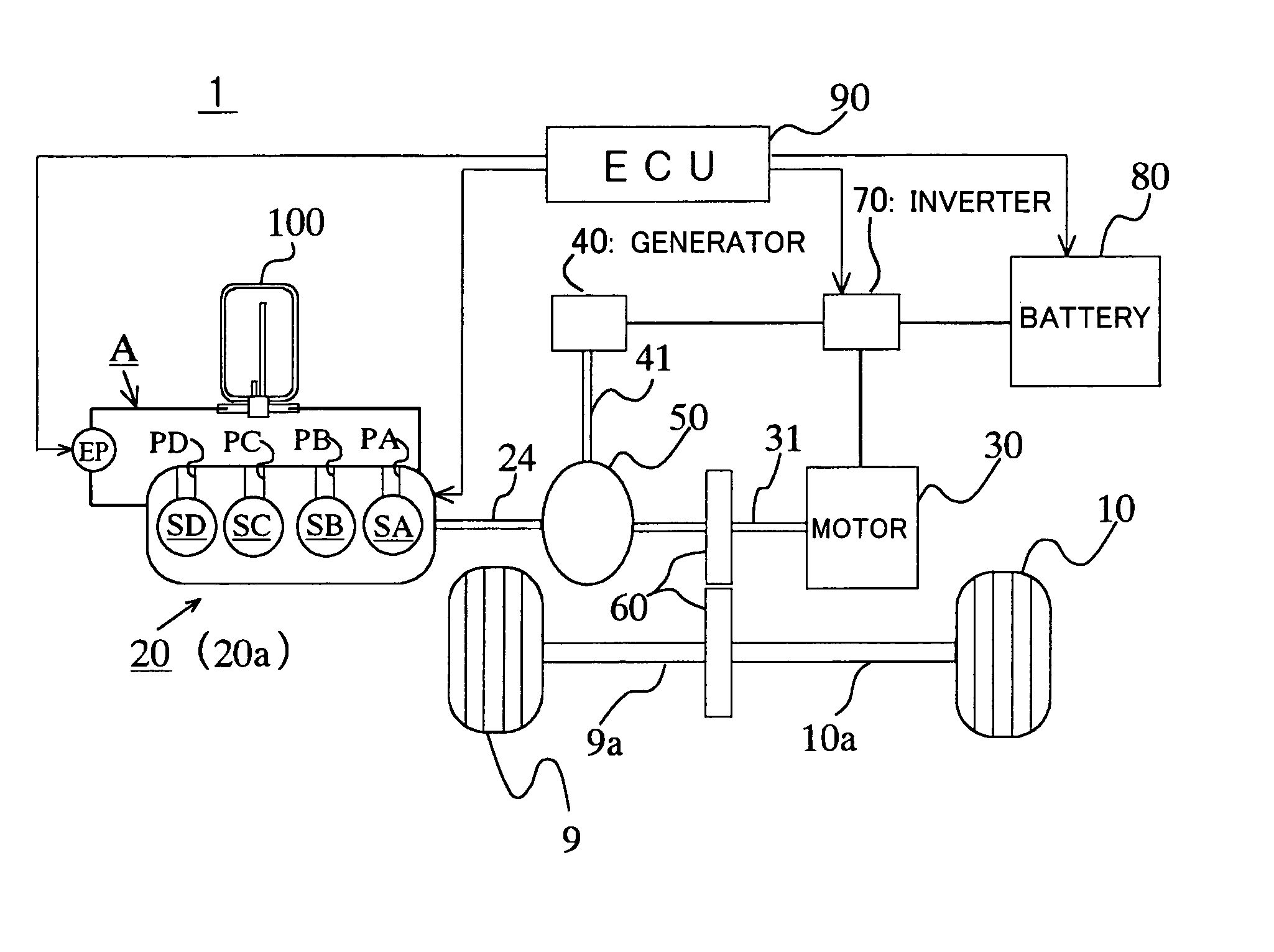
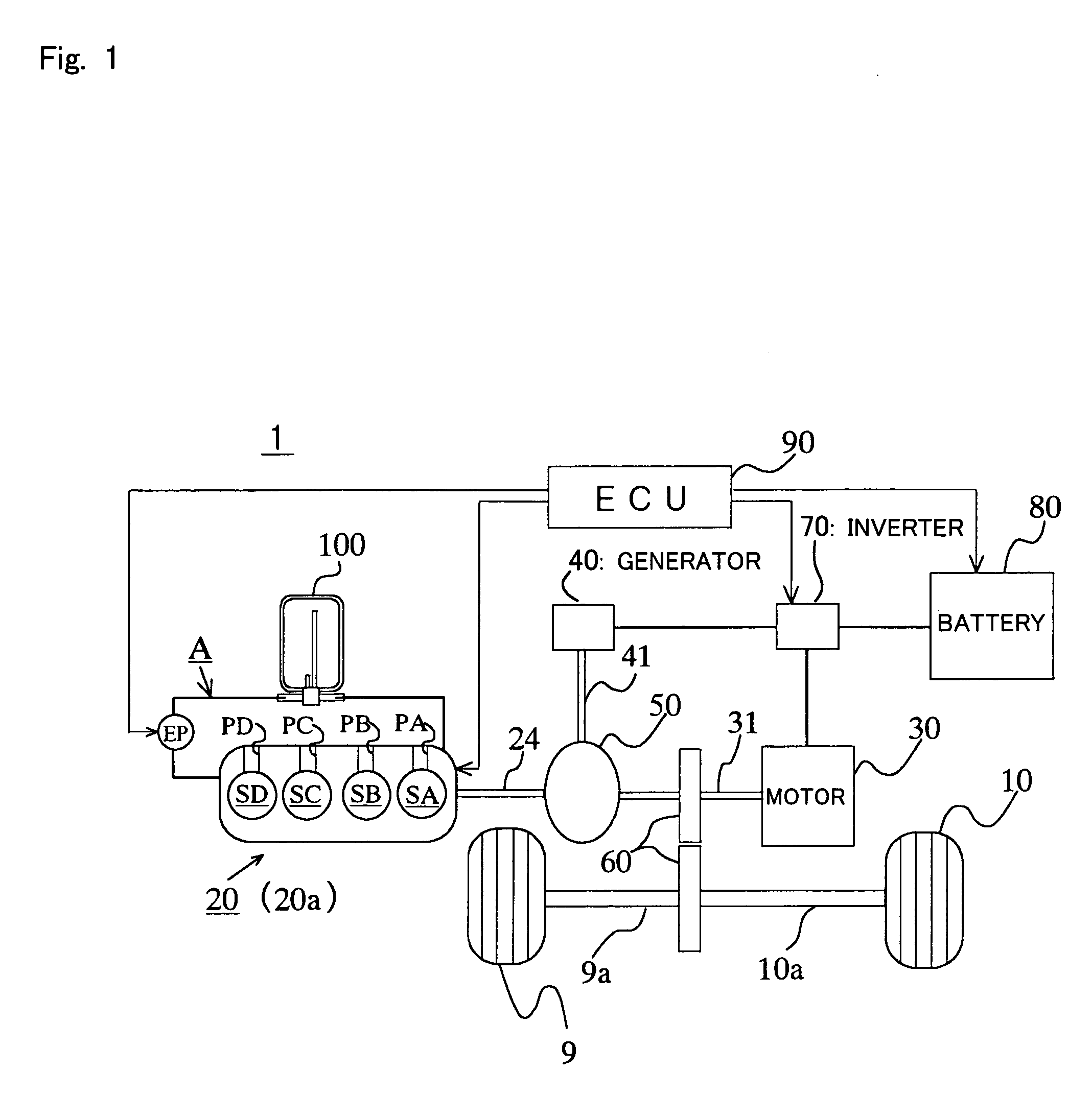
[0037] As shown in FIG. 1, a hybrid engine system (hereinafter referred to simply as an engine system), generally designated at reference numeral 1, includes, as its main component elements, an internal combustion engine 20, a motor 30 (part of a motor generator), a generator 40 (part of the motor generator), a power dividing mechanism 50, a speed reducer 60, an inverter 70, a battery 80, an electronic control unit (ECU) 90, a thermal storage tank 100, etc. Here, note that FIG. 9 is a block diagram that shows the relation between such component parts in this embodiment.

[0038] The internal combustion engine 20 has four cylinders SA, SB, SC, SD arranged serially in a single line. In a cylinder head 20a of the internal combustion engine 20, there are formed a pl...


PUM


Abstract

An engine system with a thermal storage device is capable of efficiently supplying heat from a thermal storage device to an internal combustion engine. The engine system (1) equipped with the thermal storage tank (100) supplies the hot water stored in the thermal storage tank (100) to a cylinder head (20a) of the internal combustion engine (20) before the starting thereof. At this time, an electronic control unit (90) sets a target value of the temperature of the internal combustion engine (20) at the start of the hot water supply in such a manner that the lower the temperature of the internal combustion engine (20), the lower does the target value become. As a result, a variation in combustion states between cylinders can be suppressed at the starting of the internal combustion engine (20).

Description

BACKGROUND OF THE INVENTION [0001] 1. Field of the Invention [0002] The present invention relates to an engine system equipped with an internal combustion engine as a drive source, and in particular, to such an engine system equipped with a thermal storage device that supplies the heat stored in itself to the internal combustion engine. [0003] 2. Description of the Related Art [0004] There has hitherto been known an engine system having an internal combustion engine as a drive source, and a thermal storage device (thermal storage tank) that serves to accumulate or store cooling water heated by the internal combustion engine during operation thereof in a heat retaining state so as to utilize it for facilitating the subsequent warm-up of the internal combustion engine. In an engine system described in a first patent document (Japanese patent application laid-open No. 2002-122061) for example, the cooling water (hot water) accumulated or stored in a thermal storage tank is supplied to ...

Claims


Application Information

Patent Timeline
IPC IPC(8): B60K6/24B60K6/445B60W10/30B60W20/00F01P3/20F01P7/14F01P7/16F01P11/16F01P11/20F02D45/00F02N19/10
CPCB60K1/02Y02T10/6239B60K6/445B60L2240/445B60L2270/44B60W10/06B60W20/00B60W2510/0676F01P7/167F01P11/20F01P2007/146F01P2011/205F01P2050/24F02N19/10B60K6/365Y02T10/62B60W20/15
Inventor KUZE, YASUHIROOTSUKA, TAKAYUKIICHINOSE, HIROKIKINUGASA, YUKIO
Owner TOYOTA JIDOSHA KK
Learn More