Flip chip light emitting diode devices having thinned or removed substrates

a light-emitting diode and flip-chip technology, applied in the field of electronic arts, can solve the problems of compromising device yield, difficult to achieve intimate bonding between the epitaxial layer stack and the transparent substrate over large areas, and reducing the thickness of the growth substrate of the device di

Active Publication Date: 2005-02-03
GE LIGHTING SOLUTIONS LLC
View PDF23 Cites 167 Cited by
  • Summary
  • Abstract
  • Description
  • Claims
  • Application Information

AI Technical Summary

Benefits of technology

The patent describes a method for making a flip-chip light emitting diode device. The method involves depositing layers on a growth substrate to create an epitaxial wafer, then fabricating multiple LED devices on this wafer. The wafer is then diced to create individual devices, which are then flip-chip bonded to a mount using electrodes and bonding pads. After bonding, the growth substrate is removed to make the device thinner. The technical effect of this method is to create a more efficient and compact LED device that is easier to mount and has improved thermal performance.

Problems solved by technology

The technical problem addressed in this patent is the optical losses that occur when a flip-chip bonded light emitting diode is mounted on a substrate that absorbs light. This can be a problem even when using an optically transparent substrate. The current methods for reducing these losses, such as transferring the epitaxial layers to a new substrate or using a temporary support wafer, have limitations such as difficulty in achieving intimate bonding and introducing optical losses. The present invention aims to improve the process of mounting flip-chip bonded light emitting diodes on a substrate to reduce optical losses and improve device yield.

Method used


Image

  • Flip chip light emitting diode devices having thinned or removed substrates
  • Flip chip light emitting diode devices having thinned or removed substrates
  • Flip chip light emitting diode devices having thinned or removed substrates

Examples


Embodiment Construction

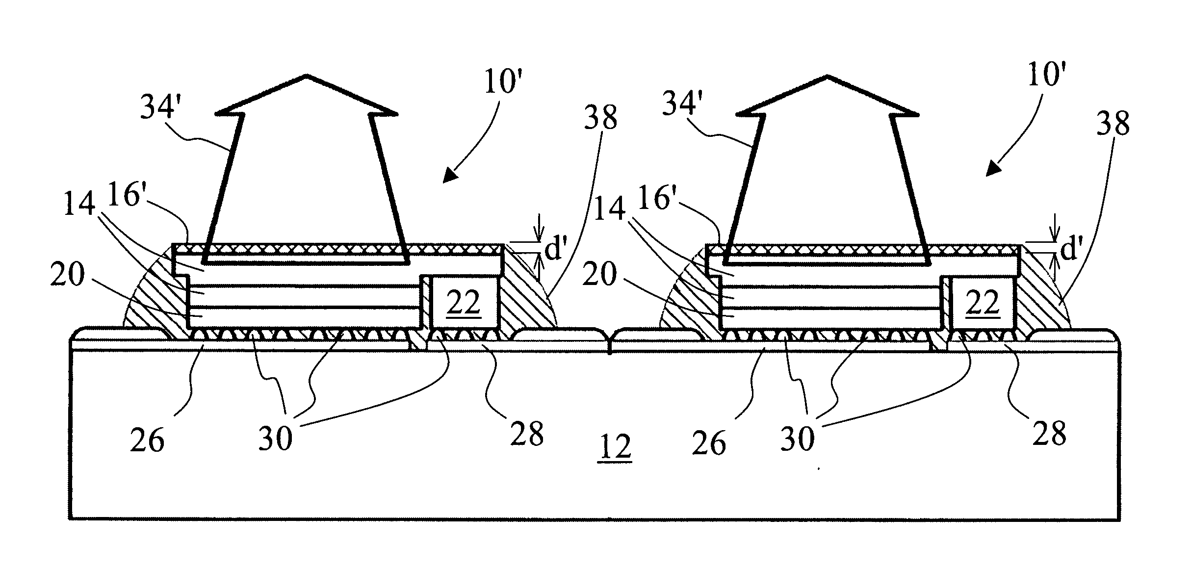
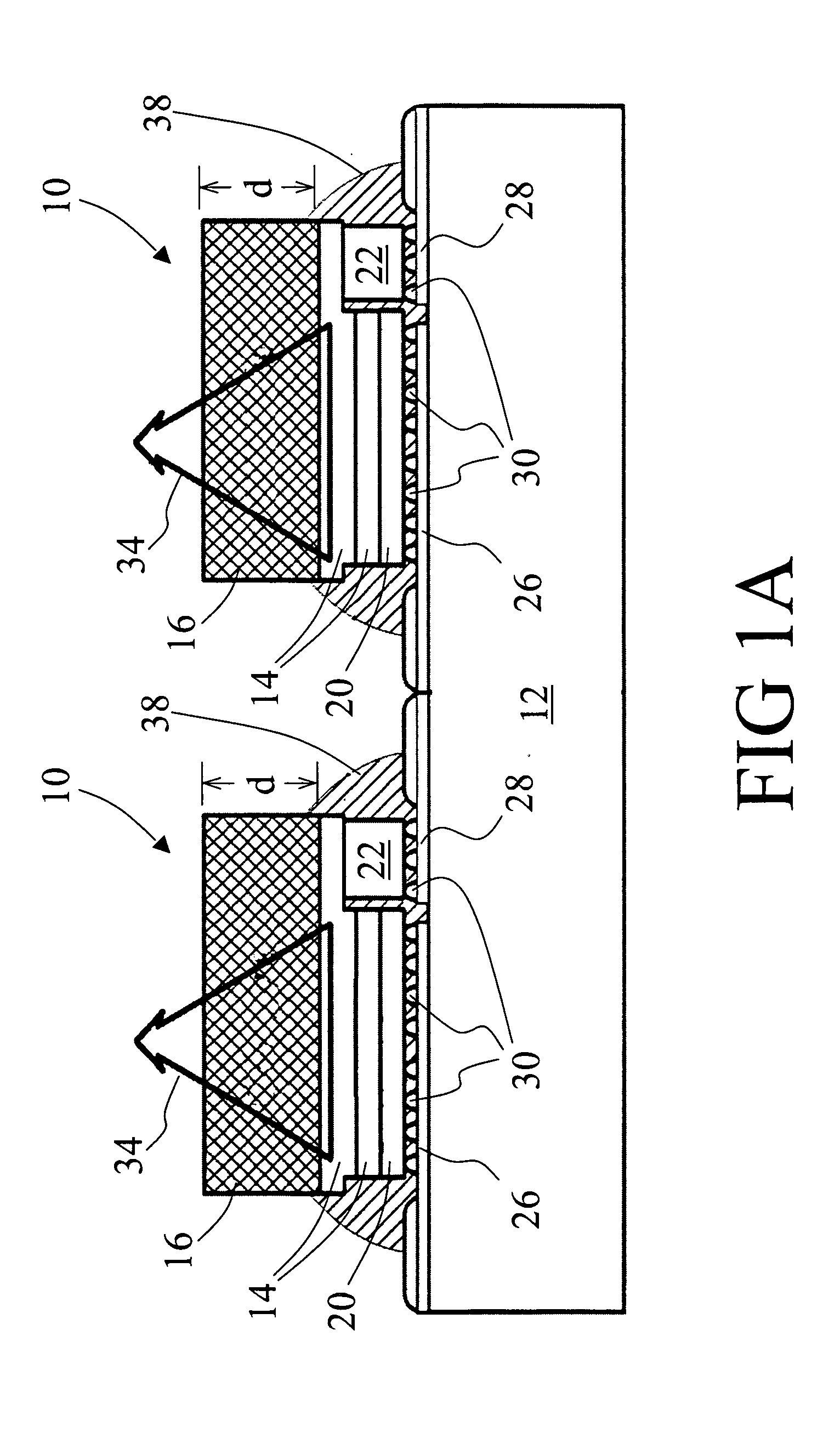
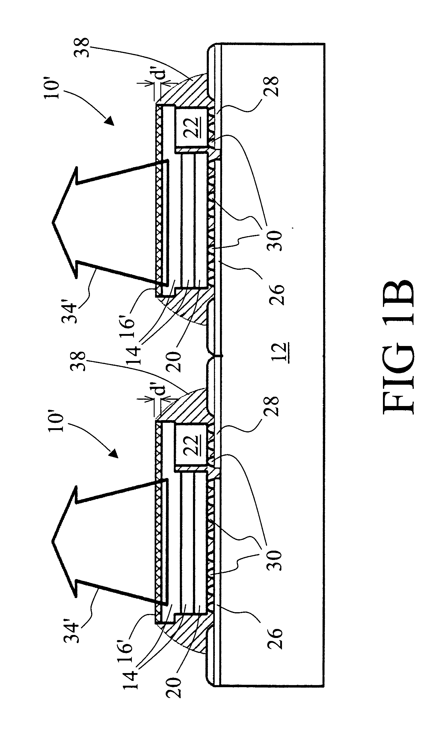
[0020] With reference to FIG. 1A, two exemplary flip chip bonded light emitting diode device die 10 are shown mounted in flip-chip fashion on a mount 12. Each exemplary light emitting diode device die 10 includes a semiconductor device layers stack 14 that is epitaxially deposited on a growth substrate 16. The epitaxial device layers stack 14 defines a light emitting diode device such as a group III nitride ultraviolet or blue light emitting diode, a group III phosphide visible-emission light emitting diode, a group III arsenide vertical cavity surface emitting laser diode, or the like.

[0021] In FIG. 1A, the semiconductor layers stack 14 has two exemplary layers corresponding to a simple p / n diode; however, those skilled in the art will appreciate that more complex semiconductor layers stacks can be employed. In a vertical cavity surface emitting laser diode, for example, the layers stack can include dozens of layers that define Bragg reflectors, claddings, and a complex multi-quan...


PUM


Abstract

In a method for fabricating a flip-chip light emitting diode device, epitaxial layers (14, 114) are deposited on a growth substrate (16, 116) to produce an epitaxial wafer. A plurality of light emitting diode devices are fabricated on the epitaxial wafer. The epitaxial wafer is diced to generate a device die (10, 110). The device die (10, 110) is flip chip bonded to a mount (12, 112). The flip chip bonding includes securing the device die (10, 110) to the mount (12, 112) by bonding at least one electrode (20, 22, 120) of the device die (10, 110) to at least one bonding pad (26, 28, 126) of the mount (12, 112). Subsequent to the flip chip bonding, a thickness of the growth substrate (16, 116) of the device die (10, 110) is reduced.

Description


Claims


Application Information

Patent Timeline
Owner GE LIGHTING SOLUTIONS LLC
Why Eureka
Try Eureka