Organic EL panel drive circuit and organic EL display device

a drive circuit and drive circuit technology, applied in the direction of lighting devices, instruments, light sources, etc., can solve the problems of variable luminance, difficult drive control, and luminance variation on the display device screen of organic el, so as to reduce the variation of drive current, reduce the variation of luminous intensity, and high drive current precision

Active Publication Date: 2005-02-03
ROHM CO LTD
View PDF2 Cites 23 Cited by
  • Summary
  • Abstract
  • Description
  • Claims
  • Application Information

AI Technical Summary

Benefits of technology

[0021] An object of the present invention is to provide an organic EL drive circuit capable of reducing variation of drive current in a driver IC thereof for current-driving an organic EL panel.
[0022] Another object of the present invention is to provide an organic EL drive circuit capable of reducing luminous variation on a screen of an organic EL display device due to difference in characteristics between driver ICs for current-driving an organic EL panel.
[0023] A further object of the present invention is to provide an organic EL display device capable of reducing luminous variation of a screen of an organic EL display device due to difference in characteristics between driver ICs for current-driving an organic EL panel.
[0026] Therefore, there is no need of proving a resistor circuit in the input side of the control circuit, so that the organic EL drive circuit is not influenced by variation of resistance value of the resistor circuit. Therefore, it is possible to precisely make the output current of the output side transistor equal to the reference current or the current corresponding thereto.
[0027] Further, the precise output currents of the output side transistors or currents corresponding thereto are outputted externally of the column driver IC and used as a reference current of a next stage, that is, a slave driver IC. When the slave driver IC has the same circuit construction as that of the master, that is, first stage driver IC, it is possible to precisely control the output currents of the output side transistors of the slave driver IC to the reference current or current corresponding to the reference current. Thus, variation of the drive currents outputted to the respective terminal pins is reduced to thereby supply totally highly precise drive currents to the terminal pins.
[0028] As a result, it becomes possible to reduce variation of drive current in a column driver IC for driving an organic EL panel of a portable telephone set, etc., even when the number of terminal pins is increased and, further, it becomes possible to reduce luminous variation on a screen of an organic EL panel due to difference in characteristics between the column driver ICs for driving the organic EL panel.

Problems solved by technology

A known problem of the organic EL display device is that variation of luminance becomes considerable when a voltage drive is applied to the organic EL display device as in a liquid crystal display device and the drive control becomes difficult due to the difference in sensitivity between R (red), G (green) and B (blue).
Therefore, there is a problem that luminance variation occurs on a screen of an organic EL display device due to difference in characteristics between the column IC drivers, particularly, due to variation of drive circuits thereof.
Therefore, it is difficult to make actual output currents of the chips precisely equal to each other.
In view of this requirement, a problem occurs in the drive current control technique, in which paired resistors are utilized.
Therefore, requirements of S / N ratio and of preciseness of the drive current of the active matrix type organic EL drive circuit become more severe than those of the passive matrix type organic EL drive circuit.

Method used


Image

  • Organic EL panel drive circuit and organic EL display device
  • Organic EL panel drive circuit and organic EL display device
  • Organic EL panel drive circuit and organic EL display device

Examples


Embodiment Construction

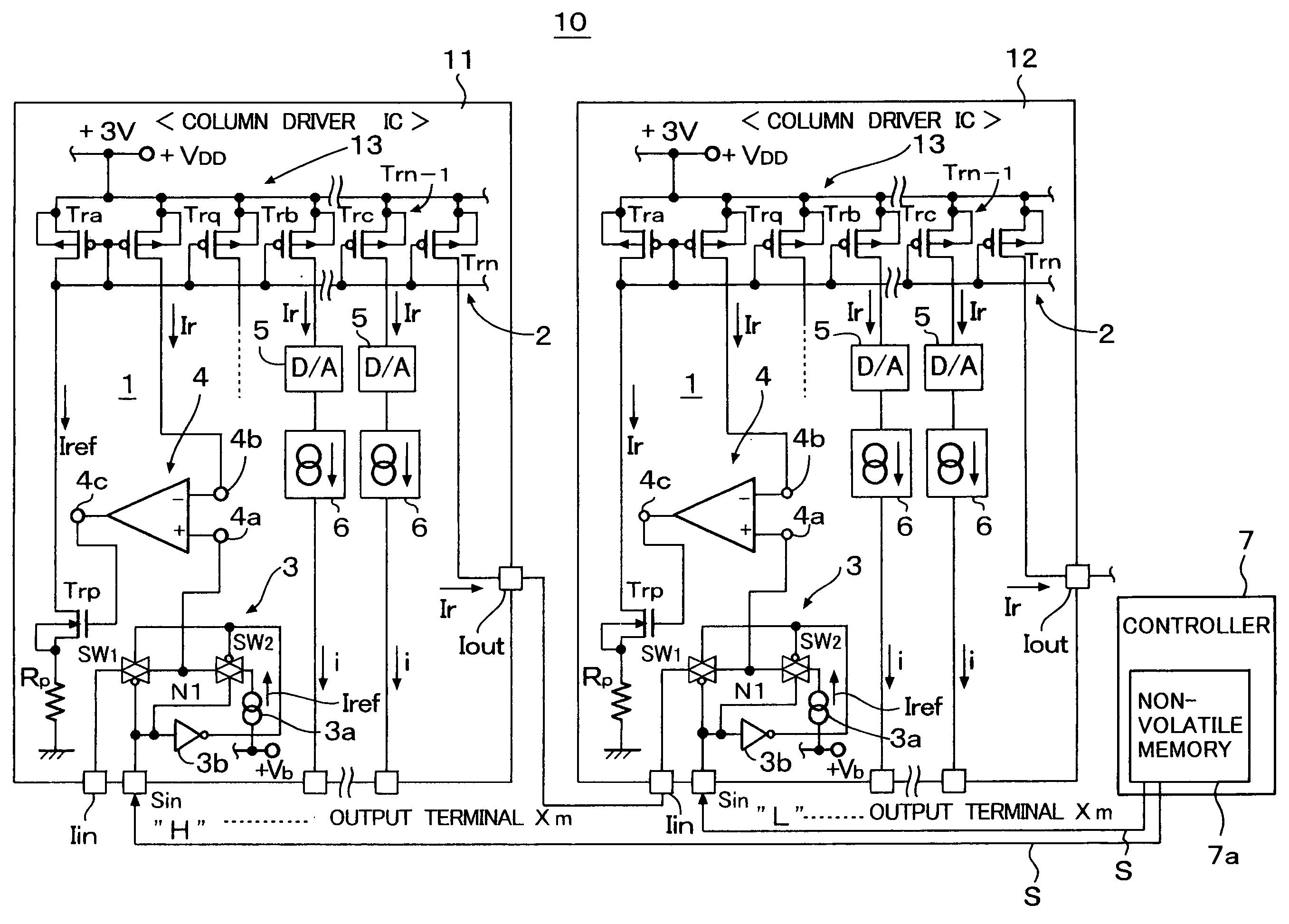
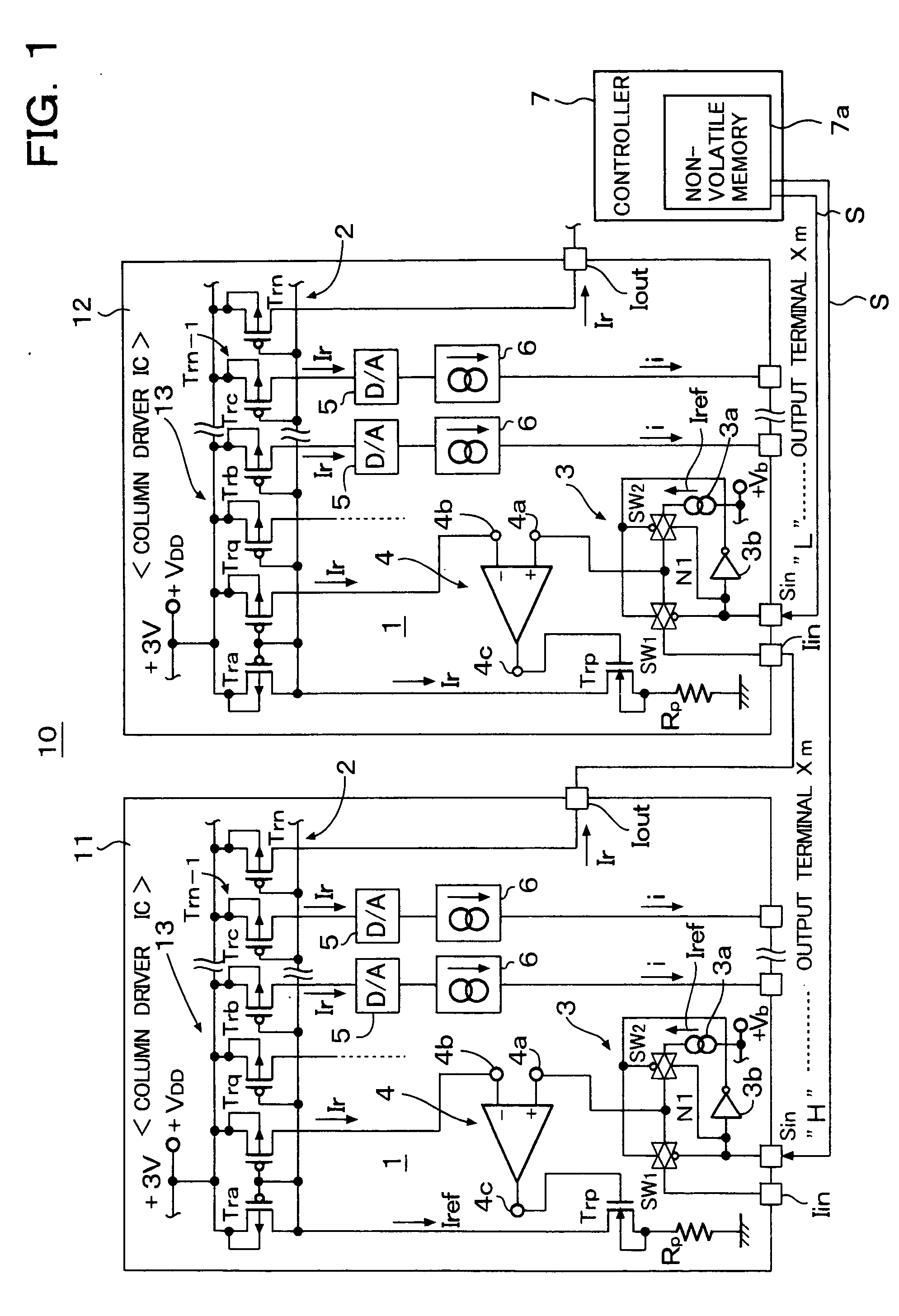
[0032]FIG. 1 is a circuit diagram of a column driver of an organic EL panel, according to an embodiment of the present invention. In FIG. 1, an organic EL panel drive circuit 10 includes column driver ICs 11 and 12.

[0033] Each of the column driver ICs 11 and 12 includes a reference current generator circuit 1 and a current output circuit 2.

[0034] The column driver IC 11 is a master chip column driver and the column driver IC 12 is a slave chip column driver and has substantially the same circuit construction as that of the column driver IC 11.

[0035] Differences between the column driver ICs 11 and 12 are that ON / OFF operation of analog switches (transmission gates) of the drivers 11 and 12, which are connected to input terminals Iin, are opposite, that the master chip driver IC 11 supplies a reference drive current Ir, which corresponds to a reference current Iref generated by the reference current generator circuit 1 of the column driver IC 11, to the slave chip driver IC 12 and...


PUM


Abstract

A transistor for detecting current generated by an output side transistor of a current mirror circuit of an organic EL panel drive circuit and a control circuit including a current driven input stage and an output stage for driving the input side transistor of the current mirror circuit are provided. The input stage of the control circuit receives the detected current and a certain reference current and the output stage of the control circuit generates a drive current, which corresponds to a difference between the detected current and the certain reference current and drives the input side transistor of the current mirror circuit. The control circuit controls the detected current in such a manner that it becomes equal to the reference current and the current distributed to terminal pins of an organic EL panel becomes the reference current or a current corresponding thereto.

Description

BACKGROUND OF THE INVENTION [0001] 1. Field of the Invention [0002] The present invention relates to an organic EL element drive circuit and an organic EL display device using the same organic EL element drive circuit. In particular, the present invention relates to an organic EL element drive circuit capable of reducing variation of drive current in a driver IC for current-driving an organic EL panel for use in a portable telephone set, etc., and reducing luminous variation on a screen of an organic EL display device due to difference in characteristics between driver ICs and, particularly, suitable for a high luminous color display and an organic EL display device using the same organic EL element drive circuit. [0003] 2. Description of the Related Art [0004] Since an organic EL display device can perform a high luminance display due to spontaneous light emission, the organic EL display device is suitable for use in a display device whose display screen size is small and is expect...

Claims


Application Information

Patent Timeline
Patent Type & Authority Applications(United States)
IPC IPC(8): G09G3/30G09G3/32H05B33/26
CPCG09G3/3216G09G3/3225G09G2320/0233G09G2310/027G09G3/3283G09G3/30
Inventor ABE, SHINICHIMAEDE, JUNFUJIKAWA, AKIO
Owner ROHM CO LTD
Why Eureka
Try Eureka