
Image processing apparatus, image processing method, and computer program

a technology of image processing and image quality, applied in the direction of image enhancement, digital output to print units, instruments, etc., can solve the problems of insufficient transfer or inadequate fixing, damage to the printer engine, toner spatter and degradation of image quality, etc., to achieve the effect of improving image quality

Inactive Publication Date: 2005-02-03
CANON KK
View PDF33 Cites 17 Cited by
  • Summary
  • Abstract
  • Description
  • Claims
  • Application Information

AI Technical Summary

Benefits of technology

[0011] To address one or more of the aforementioned disadvantages and drawbacks, in one aspect, the present invention regulates the amount of coloring material for each media type in a raster image processing unit. In another aspect, the present invention can regulate the amount of the coloring material when a predetermined media type does not match a media type that is to be used for output, thereby protecting printer engines and providing improved image quality.
[0012] In a further aspect, the present invention suitably controls the amount of a coloring material of a recording material at the time of print processing after print data is once stored on a storage medium.

Problems solved by technology

If the amount of toner application is too large, inadequate transfer or inadequate fixing occurs.
This causes toner spatter and degradation of image quality.
Damage to the printer engine can also occur.
On the other hand, if the amount of toner application is too small, an expected image quality cannot be achieved.
Thus, excessive adjustment could be executed, causing degradation of image quality.
However, the amount of toner application may be insufficient depending on the type of media used for printing data from the hard disk.
This reduces the density of the image and degrades the image quality.

Method used


Image

  • Image processing apparatus, image processing method, and computer program
  • Image processing apparatus, image processing method, and computer program
  • Image processing apparatus, image processing method, and computer program

Examples


first embodiment

[0034] First Embodiment

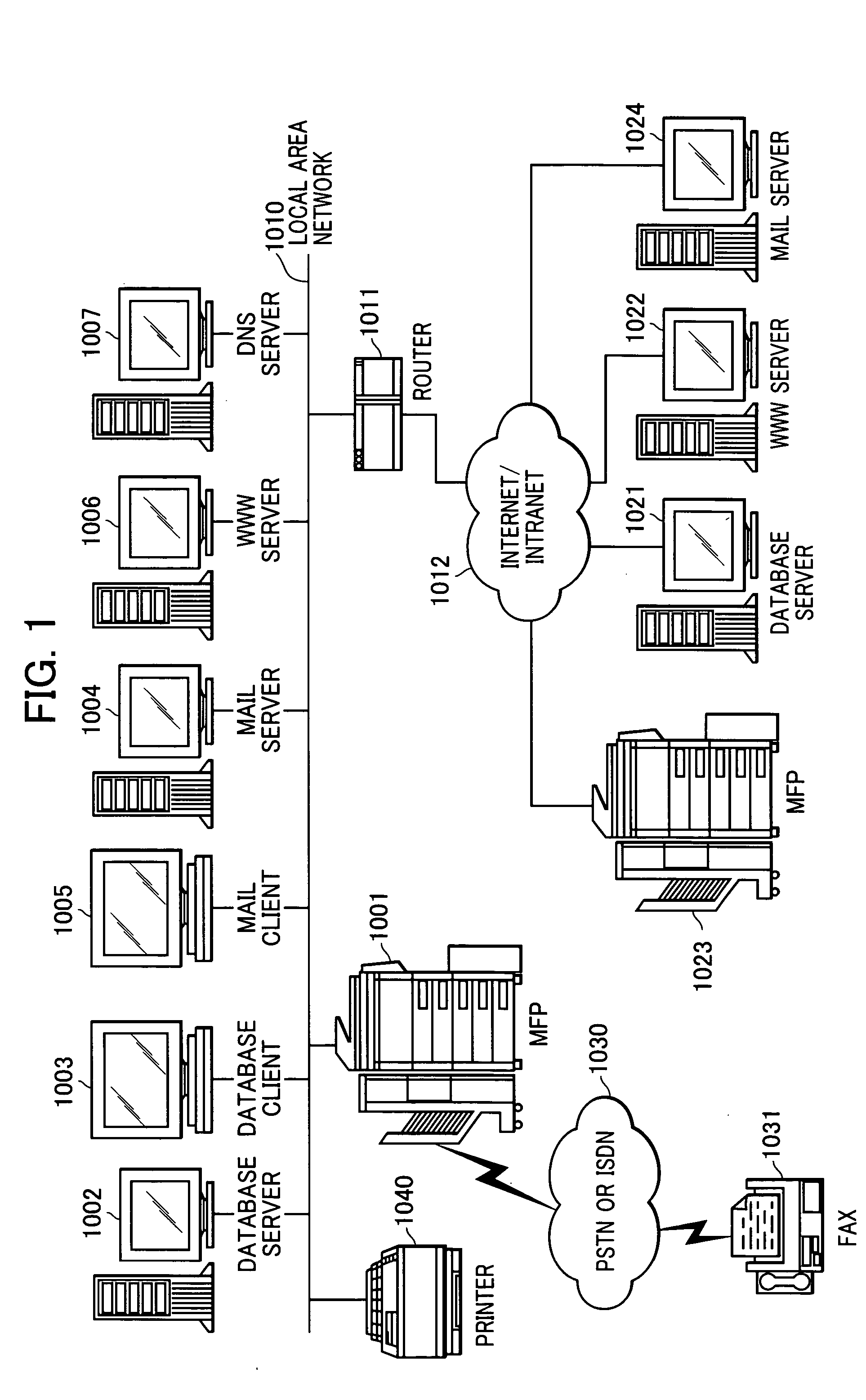
[0035]FIG. 1 shows the overall configuration of a network system according to a first embodiment of the present invention.

[0036] Referring to FIG. 1, a multi-function printer 1001 includes a scanner and a printer. The multi-function printer 1001 is capable of sending an image read by the scanner onto a local area network (LAN) 1010, and printing an image received via the LAN by the printer. Furthermore, the multi-function printer 1001 is capable of sending an image read by the scanner onto a PSTN (Public Switched Telephone Network) or ISDN (Integrated Services Digital Network) 1030 by a facsimile sending unit, and printing an image received via the PSTN or ISDN 1030. A database server 1002 manages a database of binary images and multi-valued images read by the multi-function printer 1001.

[0037] A database client 1003 associated with the database server 1002 is allowed to browse and search for image data stored in the database server 1002.

[0038] A mail serve...

second embodiment

[0100] Second Embodiment

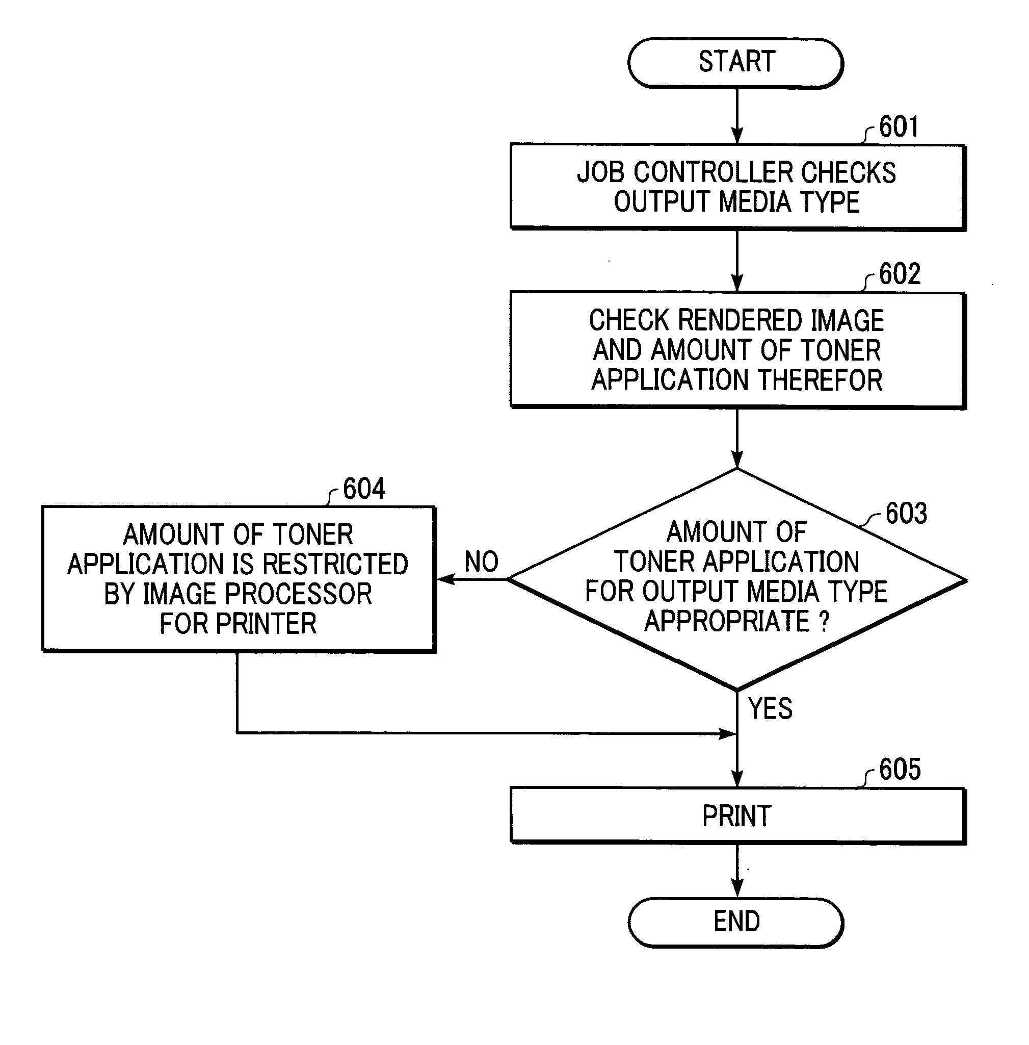
[0101] In step 501, when a job input is a box input job based on default media type information set by the user via the UI 2012, the multi-function printer 100 determines the amount of toner application suitable for the default media type. Then, in step 502, the RIP unit executes rendering according to the determined amount of toner application. In step 503, the rendered image is JPEG compressed before it is stored in the external storage device 2004 of the controller unit 2000. Information representing the amount of toner application used for rendering is also stored in the external storage device 2004 in step 503. A box input job herein refers to a job in which a rendered image is compressed by packet JPEG before the image is stored in the external storage device 2004 of the controller unit 2000. The compression method is not limited to packet JPEG, and may be other methods, e.g., JPEG 2000 or MMR (Modified Modified Read). FIG. 10 is a diagram showing contr...

third embodiment

[0103] Third Embodiment

[0104] In the first embodiment, when step 404 evaluates to No, the procedure proceeds to step 405, in which the printer image processor 2115 regulates the amount of toner application. In a third embodiment of the present invention, when step 404 evaluates to No, the job controller inputs a rendered image to the interpreter unit, switches the profile used in the CMS unit to a profile in consideration of the maximum amount of toner application for the media type of recording paper, and executes color matching for the rendered image, thereby adjusting the amount of toner application. Similarly, in the second embodiment, when step 603 evaluates to No, the printer image processor 2115 regulates the amount of toner application in step 604. In the third embodiment, when step 603 evaluates to No, the job controller inputs a rendered image to the interpreter unit, switches the profile used in the CMS unit to a profile in consideration of the maximum amount of toner app...


PUM


Abstract

An image processing apparatus includes a first determining unit for determining which medium an image is to be formed on; a second determining unit for determining an amount of a coloring material of a recording material according to the medium determined by the first determining unit; a color processing unit for executing color processing in a raster image processing unit according to the amount of the coloring material determined by the second determining unit; a comparing unit for comparing a predetermined medium with a medium that is to be used for output to determine whether these media match, after the color processing by the color processing unit; and a controlling unit for controlling whether to adjust the amount of the coloring material again according to a result of the comparison by the comparing unit.

Description

CROSS-REFERENCE TO RELATED APPLICATIONS [0001] This application claims priority from Japanese Patent Application No. 2003-203746 filed Jul. 30, 2003, which is hereby incorporated by reference. BACKGROUND OF THE INVENTION [0002] 1. Field of the Invention [0003] The present invention relates to an image processing apparatus, an image processing method, and a computer program for controlling the amount of a coloring material in a recording material in accordance with different media types. [0004] 2. Description of the Related Art [0005] Techniques for adjusting the amount of toner application in accordance with different media types in an image processing unit of a color printer in which the maximum amount of toner application is restricted are known. Such techniques are disclosed, for example, in Japanese Patent Laid-Open No. 8-98048. [0006] Usually, when a print job that has been stored in a large-capacity storage medium such as a hard disk in a printer is printed, the amount of tone...

Claims


Application Information

Patent Timeline
IPC IPC(8): G06F3/12G06K15/02G06T1/00B41J2/525H04N1/387
CPCG06K15/02G06K2215/0094G06K15/021
Inventor AKASHI, MASAMICHI
Owner CANON KK
Learn More