
Cable modem termination system with flexible addition of single upstreams or downstreams

a technology of termination system and cable modem, which is applied in the direction of data switching network, frequency-division multiplex, instruments, etc., can solve the problems of excessive expenditure and bad return on investmen

Inactive Publication Date: 2005-02-03
GOOGLE TECH HLDG LLC
View PDF21 Cites 100 Cited by
  • Summary
  • Abstract
  • Description
  • Claims
  • Application Information

AI Technical Summary

Benefits of technology

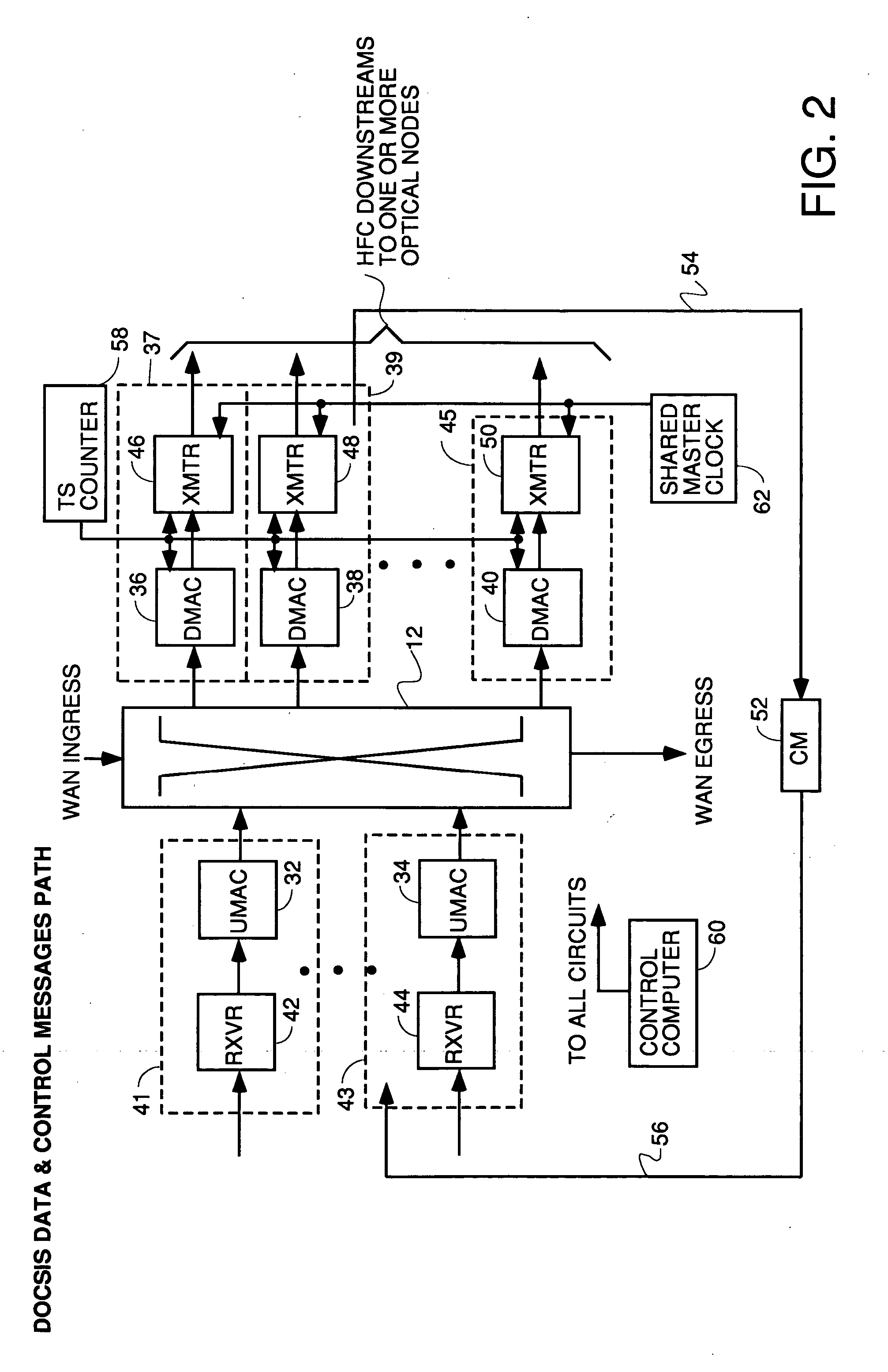
What is significant about this CMTS arrangement is the granularity and flexibility of it. What this means is that every shared upstream receiver can be on a different linecard than the downstream receiver linecards which share the upstream receiver linecard, and the packet switch can pass data and messages between the UMAC of the shared upstream and DMAC processes in each downstream in the group of downstreams which share the upstream. The upstream mappers provides the significant new ability to electronically map which optical nodes will be terminated in which upstream receivers at the CMTS and to change that mapping to add new receivers to the same upstream or add new upstreams as conditions dictate. The downstream mapper provides the significant new ability to electronically map downstream transmitters to optical nodes. The UMAC and DMAC processes are new and are written so as to cooperate with each other by exchanging data through the packet switch to allow multiple downstreams to share the same upstream and to assign more or fewer downstreams to each upstream as the need arises, and to add more upstreams or more receivers to an existing shared upstream as load balancing conditions dictate or as needed to resolve communication problems some cable modems may be having in transmitting upstream (by creating a lower throughput upstream with a lower symbol rate, more extensive forward error correction capability, etc.)

Problems solved by technology

This causes excessive expenditure and bad return on investment if all the cable operator needs is another upstream or another downstream.

Method used


Image

  • Cable modem termination system with flexible addition of single upstreams or downstreams
  • Cable modem termination system with flexible addition of single upstreams or downstreams
  • Cable modem termination system with flexible addition of single upstreams or downstreams

Examples


Embodiment Construction

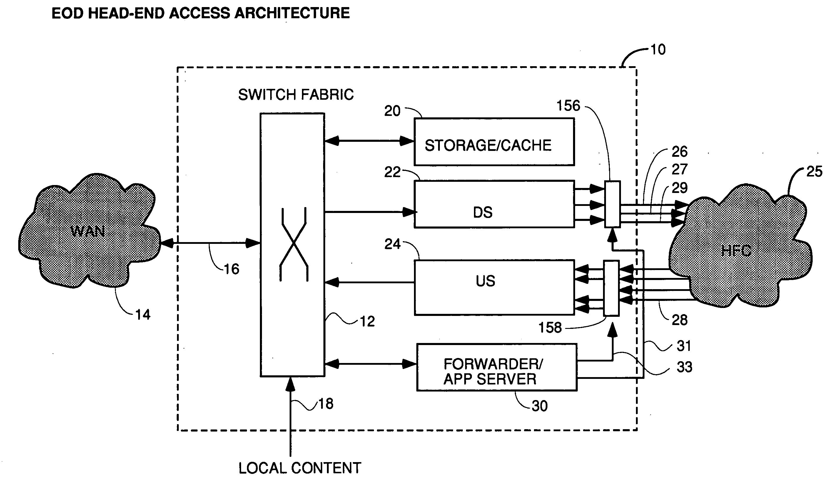
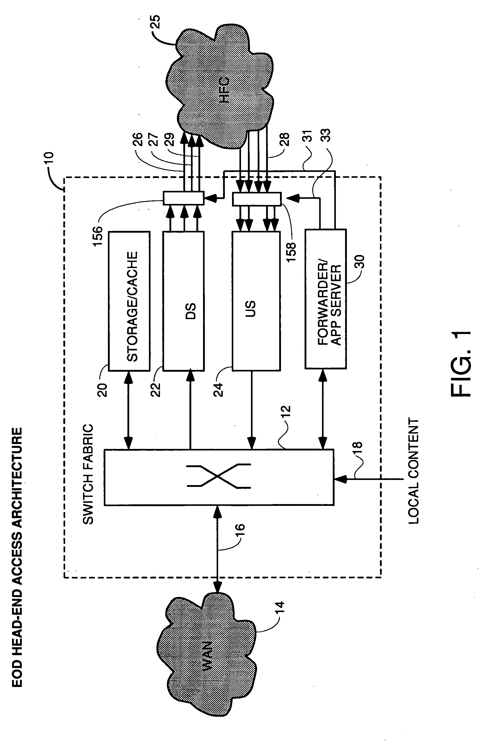
FIG. 1 is a block diagram of a new third generation CMTS architecture and having circuitry which is compliant with DOCSIS 1.0, 1.1 and 2.0 specifications, all of which are hereby incorporated by reference. The CMTS 10 is comprised of a packet switch 12 for coupling to a wide area network 14 such as the internet via data path 16, local content provider servers such as video-on-demand (VOD) servers (not shown) via data path 18. Inside the CMTS, the switch fabric is coupled to a storage / cache memory 20, one or more downstream transmitter line cards, represented collectively at 22.

The downstream transmitters each have an RF output which is coupled to one or more optical nodes (not shown) of a hybrd fiber coaxial cable system (HFC) 25 via a downstream mapper and splitter / combiner 156 (downstream mapping switch). Each downstream transmitter line card functions to transmit one or more MPEG transport streams and DOCSIS downstreams on a QAM modulated downstream channel to one or more optica...


PUM


Abstract

A cable modem termination system is disclosed with flexible mapping of upstreams to downstreams and flexible mapping of downstreams to optical nodes and optical nodes to upstream receivers and the ability to add singe upstreams or downstreams as needed for load balancing. Multiple downstreams can share the same upstream. Multiple receivers can be coupled to the same upstream. Monitoring of upstream performance for overperforming or underperforming modems can be carried out, and new upstreams with higher and / or lower throughtput can be created to service the overperformers and / or underperformers. Modems can be grouped into logical groups with different performance levels and serviced by different upstreams or different upstream logical channels on the same upstream physical channel.

Description

BACKGROUND OF THE INVENTION In today's cable modem termination systems (CMTS), there is a fixed ratio of downstreams to upstreams on each expansion card. This means that a prior art expansion card for a CMTS has one downstream transmitter with all the media access control and physical layer circuitry needed to transmit a DOCSIS downstream on a hybrid fiber coaxial cable (HFC). The prior art expansion cards also has four upstream receivers, each with the MAC and physical layer circuitry needed to interface with one hybrid fiber coaxial cable medium. Other prior art expansion cards have different ratios of upstreams to downstreams. However, the need for additional upstream and downstream capacity does not change in the same fixed ratio as the cards. Thus, when upstream or downstream installed capacity is exceeded, another card must be added which adds another downstream and four upstreams. This causes excessive expenditure and bad return on investment if all the cable operator needs ...

Claims


Application Information

Patent Timeline
IPC IPC(8): H04J3/06H04J13/00H04L12/417H04L12/56
CPCH04J3/0682H04W28/10H04W24/00H04L12/407
Inventor RAKIB, SELIM SHLOMOAZENKO, YEHUDA
Owner GOOGLE TECH HLDG LLC
Learn More