Three-wire three-level digital interface

a three-level digital interface and receiver technology, applied in digital transmission, diversity/multi-antenna systems, baseband system details, etc., can solve the problems of difficult physical implementation, rfic frequency synthesizer power consumption becoming comparable to the power consumption of phase locked loop, etc., to avoid the introduction of parasitic capacitance of the common node, high noise immunity, and high noise immunity

Active Publication Date: 2016-11-08
TELEFON AB LM ERICSSON (PUBL)
View PDF6 Cites 0 Cited by
  • Summary
  • Abstract
  • Description
  • Claims
  • Application Information

AI Technical Summary

Benefits of technology

[0017]The receiver can enable twelve different states of voltages or currents, that is, twelve different permutations of voltage or current values, at the first, second and third input terminals to be received and distinguished. Therefore, a high number of bits can be represented by each state, thereby facilitating high speed data transmission, or enabling a low clock speed and data symbols of long duration to be employed. In general, a high speed digital interface may require precise matching between the input impedance of a receiver and the source impedance presented to the inputs of the receiver, in order to prevent input signals from being reflected. However, by enabling a low clock speed and low symbol rate, the disclosed receiver can relax the requirement for precise matching, thereby enabling the input impedance of the receiver to be increased, enabling the receiver to operate with lower input currents, and reducing power consumption. The receiver also enables a high immunity to noise by ensuring that the minimum voltage difference that is required to be detected within the receiver is high. The receiver is arranged to detect voltage differences, and so avoids the need to generate a voltage reference, such as midway between two supply voltage rails, with which to compare these voltages. This can reduce complexity and improve reliability. The receiver is able to operate with three-level input voltages, where the input voltages are selected from two signalling voltages and one intermediate voltage midway between the two signalling voltages. Where the two signalling voltages have the same magnitude and opposite polarities, and the intermediate voltage may be zero.
[0028]Alternatively, with the triangular configuration, the first, second and third resistive elements may have substantially equal resistance, and the seventh, eighth and ninth resistive elements may each have a substantially equal resistance double the resistance of the first, second and third resistive elements. This feature enables a high noise immunity and enables the minimum voltage between the non-inverting input and inverting inputs of each of the first to sixth comparators to be the same for each of the first to sixth comparators.

Problems solved by technology

The current MIPI DigRF v4 draft interface requires a 5.2 GHz clock for transmitting data in the LTE 20+20+20 case, denoting aggregation of three 20 MHz portions of spectrum, rendering the physical implementation very challenging.
This means that the power consumption of the phase locked loop becomes comparable to the power consumption of the RFIC frequency synthesizer.

Method used


Image

  • Three-wire three-level digital interface
  • Three-wire three-level digital interface
  • Three-wire three-level digital interface

Examples


Embodiment Construction

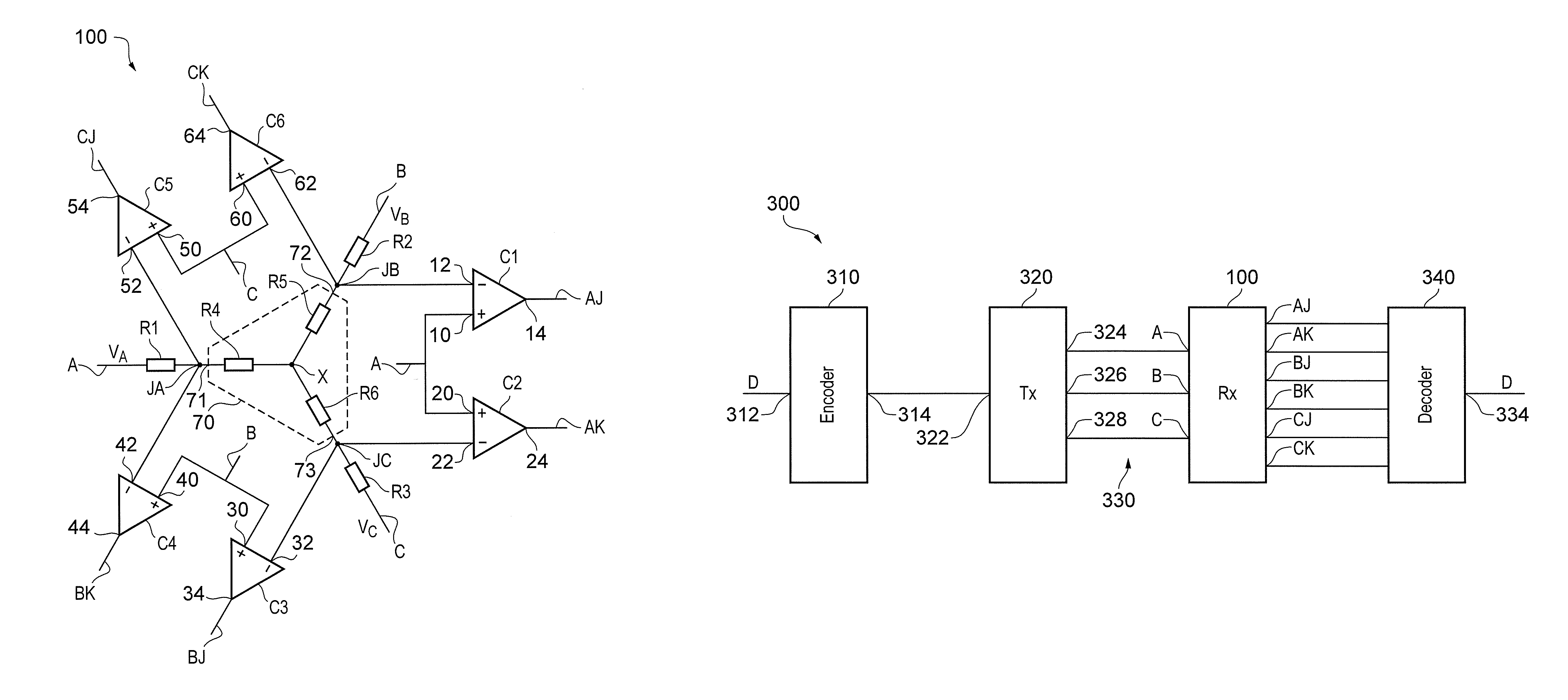
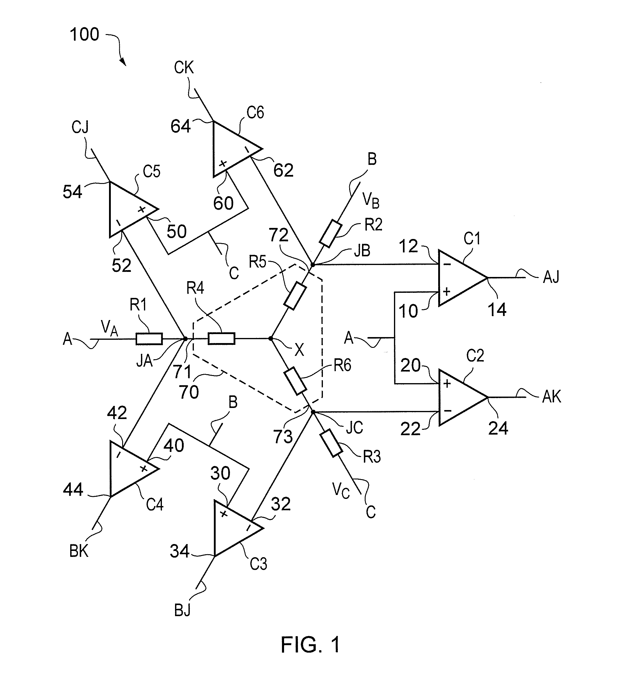
[0003]According to a first aspect there is provided a receiver for a three-wire digital interface, comprising:

[0004]first, second and third input terminals;

[0005]first, second, third, fourth, fifth and sixth output terminals;

[0006]first, second and third junction nodes;

[0007]a first resistive element coupled between the first input terminal and the first junction node;

[0008]a second resistive element coupled between the second input terminal and the second junction node;

[0009]a third resistive element coupled between the third input terminal and the third junction node;

[0010]a network comprising first, second and third network terminals coupled to, respectively, the first, second and third junction nodes, the network having substantially the same impedance between all pairs of the first, second and third network terminals;

[0011]a first comparator having a non-inverting input coupled to the first input terminal, an inverting input coupled to the second junction node, and an output co...


PUM


Abstract

A receiver for a three-wire digital interface, a method for operating a three-wire digital interface, a signalling system comprising the receiver, and a wireless communication device comprising the signalling system. The receiver for a three-wire digital interface comprises a first resistive element coupled between a first input terminal and a first junction node, a second resistive element coupled between a second input terminal and a second junction node, and a third resistive element coupled between a third input terminal and a third junction node. A network comprising first second and third network terminals is coupled to first, second and third junction nodes. The network has substantially the same impedance between all pairs of the first, second and third network terminals.

Description

FIELD OF THE DISCLOSURE[0001]The present disclosure relates to a receiver for a three-wire digital interface, a method of operating such a three-wire digital interface, a signalling system comprising the receiver, and a wireless communication device comprising the signalling system.BACKGROUND TO THE DISCLOSURE[0002]The digital interface between radio frequency integrated circuits (RFICs) and baseband integrated circuits (BBIC) has to support increasingly high data rates with wireless communication standards such as the Third Generation Partnership Project (3GPP) Long Term Evolution (LTE) standard employing carrier aggregation. Digital interface standards are specified by the Mobile Industry Processor Interface (MIPI) Alliance. The current MIPI DigRF v4 draft interface requires a 5.2 GHz clock for transmitting data in the LTE 20+20+20 case, denoting aggregation of three 20 MHz portions of spectrum, rendering the physical implementation very challenging. These extremely high clock rat...

Claims


Application Information

Patent Timeline
Patent Type & Authority Patents(United States)
IPC IPC(8): H04L7/00H04L25/49H04L25/02H04B7/06
CPCH04L25/4917H04B7/06H04L25/0272H04L25/0292H04L7/0079
Inventor KOLI, KIMMO
Owner TELEFON AB LM ERICSSON (PUBL)
Why Eureka
Try Eureka