Method for the production of an electrically conductive resistive layer and heating and/or cooling device

Inactive Publication Date: 2005-02-03
WATLOW ELECTRIC MFG
View PDF29 Cites 10 Cited by
  • Summary
  • Abstract
  • Description
  • Claims
  • Application Information

AI Technical Summary

Benefits of technology

[0024] One further beneficial embodiment is proposed so that the local electrical resistance of the electrically conductive resistance layer will be adjusted by means of local heat treatment. Through heating local oxides can be brought into the layer, which affects the local electrical conductivity of the material. This makes a specially precise and fine tuning of the electrical resistance possible.
[0025] It is also beneficial when the electrically conductive la

Problems solved by technology

The known method has the disadvantage that it is relatively complex and therefore th

Method used


Image

  • Method for the production of an electrically conductive resistive layer and heating and/or cooling device
  • Method for the production of an electrically conductive resistive layer and heating and/or cooling device
  • Method for the production of an electrically conductive resistive layer and heating and/or cooling device

Examples


Embodiment Construction

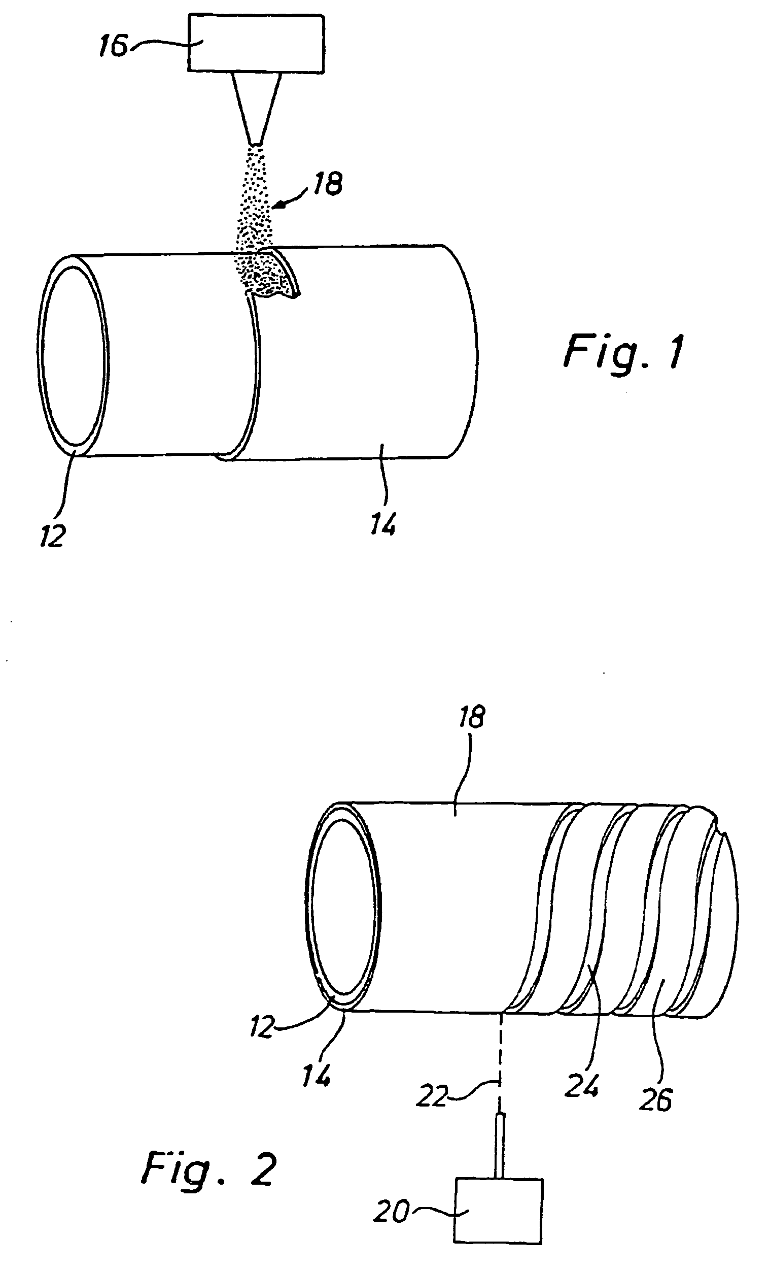
[0036]FIGS. 1 and 2 show the production of a tube shaped flow heater. On a high temperature resistant tube (12) with an electrically non-conductive material an electrically conductive layer is applied (FIG. 1). The application is conducted by means of a device (16) which is used to spray particles of Germanium (Ge) (18) on the tube (12). In this case, cold-gas-spray method is used.

[0037] In the spraying process the unmolten particles of Germanium (Ge) are accelerated to speeds of 300-1200 m / sec and sprayed on to the tube (12). On impact the Ge-particles (18) as well as the surface of the tube get deformed. Because of the impact surface-oxides of the surface of the tube (12) get broken-up. Through micro-friction because of the impact the temperature of the contact area increases and leads to micro-welding.

[0038] The acceleration of the Ge-particles (18) is done by means of a conveyor-gas whose temperature can be slightly increased. Although the Ge-powder (18) never reaches its melt...


PUM

PropertyMeasurementUnit
Electrical conductivityaaaaaaaaaa
Electrical resistanceaaaaaaaaaa
Shapeaaaaaaaaaa

Abstract

An electrically conductive resistive layer (26) is produced by thermally spraying an electrically conductive material (18) onto the surface of a non-conductive substrate (12). Initially, the material layer (14) arising therefrom has no desired shape. The material layer (14) is then removed (24) in certain areas so that an electrically conductive resistive layer (26) having said desired shape is produced.

Description

CROSS-REFERENCE TO RELATED APPLICATIONS [0001] The present application is a continuation of PCT application number PCT / EP02 / 14310, titled “Method for the Production of an Electrically Conductive Resistive Layer and Heating and / or Cooling Device” filed Dec. 16, 2002, which claims priority from German application number DE 10162276.7, filed Dec. 19, 2001.FIELD OF THE INVENTION [0002] The invention at first covers a method to produce an electrically conductive resistance layer on which an electrically conductive material will be applied, by means of thermal spraying, to a non conductive substrate. BACKGROUND OF THE INVENTION [0003] Such a method is already known from the DE 198 10 848 A1 patent. This patent describes a heating element which is produced by applying on the surface of a substrate through a plasma-spray method or an electrical arcing method band-shaped layers of an electrical conductive and resistance creating material. To achieve the desired shape of the electrical conduc...

Claims


Application Information

Patent Timeline
IPC IPC(8): C23C4/01C23C4/08H01C17/24
CPCC23C4/005C23C4/08C23C4/18C23C30/00Y10T29/49099H01C17/245H05B3/46C23C24/04H01C17/24C23C4/01C23C4/06C23C4/16F24H1/142Y10T29/49083
Inventor RUSSEGGER, ELIAS
Owner WATLOW ELECTRIC MFG
Why Eureka
Try Eureka