Multiple zone, high-capacity geo-composite drainage structures and methods suitable for high friction angle applications

a geo-composite and drainage structure technology, applied in the field of geo-composite drainage structures and high-capacity geo-composite drainage structures, can solve the problems of limited use, high cost, and difficulty in maintaining or increasing desirable flow characteristics, and achieves the effect of reducing unit costs, maintaining or increasing desirable flow characteristics, and high frictional properties

Inactive Publication Date: 2005-02-03
IANNIELLO PETER J
View PDF2 Cites 28 Cited by
  • Summary
  • Abstract
  • Description
  • Claims
  • Application Information

AI Technical Summary

Benefits of technology

[0026] As one advantage of the present invention, geocomposite structures having atypically high frictional properties can be achieved at lower unit costs while maintaining or increasing desirable flow characteristics. Geonet and geocomposite structures according to the present invention are thereby suitable in those applications to complement or replace sand, stone, or gravel in civil and environmental construction projects even when harshly acidic or alkaline liquid interactions are expected and overlying or underlying geomembranes or geotextiles are utilized.
[0027] Typical characteristics of hybrid geocomposite laminates according to the invention include: a continuous upper permeable or impermeable surface, a geonet or other flow-maintaining center, and discontinuous lower layers such as strips of high-friction substrate laminated to the lower surface in such a manner that high-friction sections of the laminate interact with adjacent layers to form high-frictional areas adjacent to or between areas having lower frictional characteristics.
[0028] A flow zone (the void-maintaining portions) of a geocomposite laminate of the invention has a transmissivity rate of not less than 1×10⁻³ m2 / sec, or not less than 1.5×10⁻³ m2 / sec, preferably not less than 2.5×10⁻³ m2 / sec, more preferably not less than 4×10⁻³ m2 / sec even more preferably not less than 5×10⁻³ m2 / sec or more preferably not less than 7.5×10⁻³ m2 / sec and most preferably not less than 1×10⁻² m2 / sec when used adjacent a lower fluid-impermeable layer, and tested in accordance with ASTM D4716 at a hydraulic gradient of from 0.01 to 1.0 at a normal stress of not less than 100 psf or not less than 500 psf, or not less than 1,000 psf, and preferably not less than 5,000 psf or 10,000 psf, and most preferably not less than 15,000 psf with boundary conditions of soil / geotextile / geonet / geomembrane.
[0029] A friction zone (having a both upper and lower geotextile layers) of a geocomposite laminate of the invention has a transmissivity rate, when combined with an adjacent fluid-impermeable membrane, of not less than 5×10⁻⁴ m2 / sec when tested in accordance with ASTM D 4716 at a hydraulic gradient of from 0.01 to 1.0 at a normal stress of not less than 100 psf and not greater than 25,000 psf with boundary conditions of soil / geotextile / geonet / geotextile / geomembrane.
[0030] Embodiments of the invention are particularly useful for installation in slopes of significant angles because they exhibit increased resistance to movement while maintaining high transmissivity. Essentially, the weighted friction angle is an average of the two friction angle values for a laminate having both friction zones and flow zones and approximately proportional to their relative areas. Thus, while friction angles for friction zone portions of a laminate range from 18-32 degrees, friction angles for flow zone portions range from 8-10 degrees.
[0031] Accordingly, the weighted friction angle for a geocomposite according to the invention would depend upon the relative area ratios of friction zone laminate to flow zone laminate. For example, in embodiments where the ratio of flow zone area to friction zone area is 1:1, the weighted frictional angle values would be in the range of from 14 to 21 degrees. Thus, the present invention provides both desired resistance to movement, that is, increased shear resistance, as well as flow capacity increases of from 25-100% when compared with conventional laminates.

Problems solved by technology

Water is the principal cause of distress in many types of structures.
A significant disadvantage of conventional types of single-sided geocomposites relates to the fact that they can only be used in limited manners due to the lack of friction between their lower surfaces and geomembranes.
Conventional double-sided systems are similarly problematic.
Indeed, a significant disadvantage of double-sided geocomposite systems is that their low-friction surfaces act as energy dissipaters and as flow impeders, thereby undercutting the very reason to utilize such conventiuonal double-sided the products.
Conventional double-sided geocomposites, which rely on a lower layer of geocomposite adjacent all of the core element's lower surface to increase friction between the laminate and an underlying membrane, are also limited with respect to the slope angle and drainage capacity because of cover soil permeability and slope length factors which make them more prone to fail when placed at significant slope angles.

Method used


Image

  • Multiple zone, high-capacity geo-composite drainage structures and methods suitable for high friction angle applications
  • Multiple zone, high-capacity geo-composite drainage structures and methods suitable for high friction angle applications
  • Multiple zone, high-capacity geo-composite drainage structures and methods suitable for high friction angle applications

Examples


Embodiment Construction

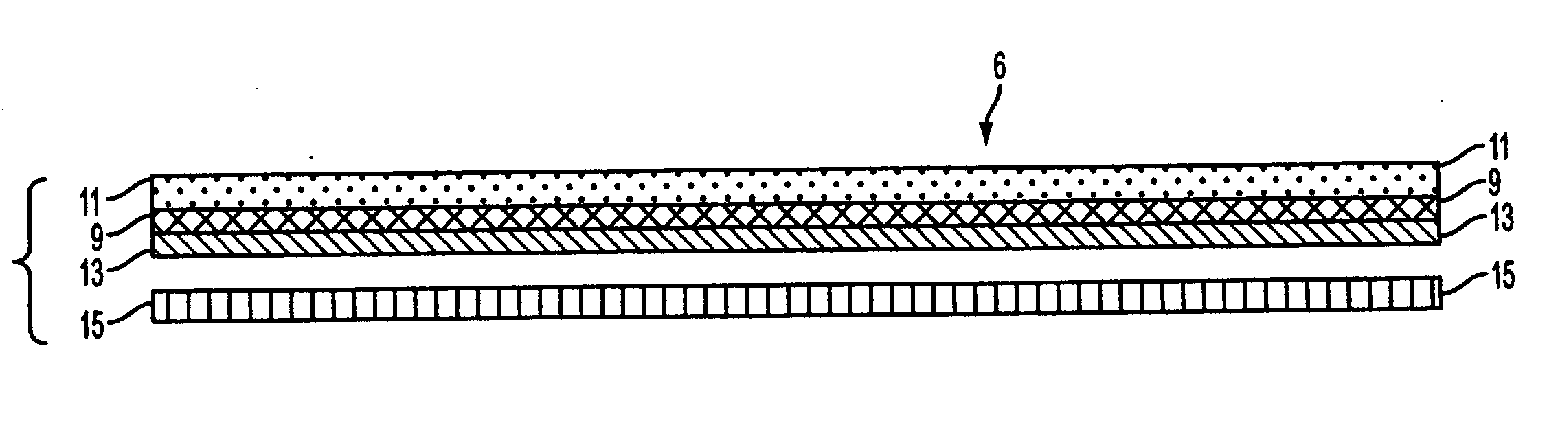
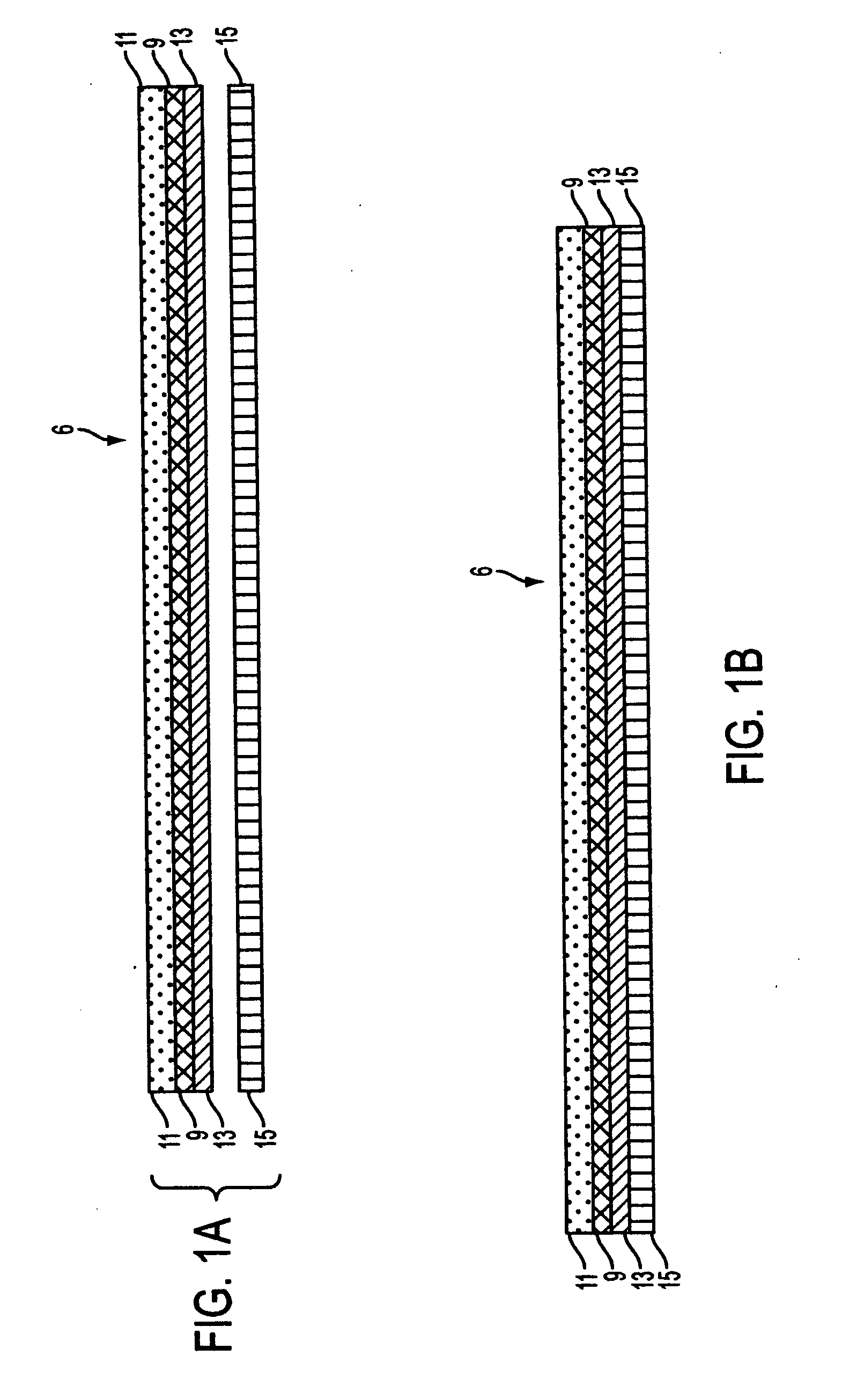
[0048] The invention may be understood both with respect to the textual description provided herein and also with respect to the accompanying figures, which are exemplary only and show only a few of the many permutations of embodiments of the present geo-stabilizers.

[0049] Within the meaning of the invention, a geonet core can be of any material so long as it provides the needed design strengths and performance characteristics. Depending upon the specific embodiment, a geocomposite of the invention can be installed with or without a geomembrane beneath it. Moreover, the numerous embodiments of the present invention can be adapted to specific uses since resistance to movement is provided in several different aspects.

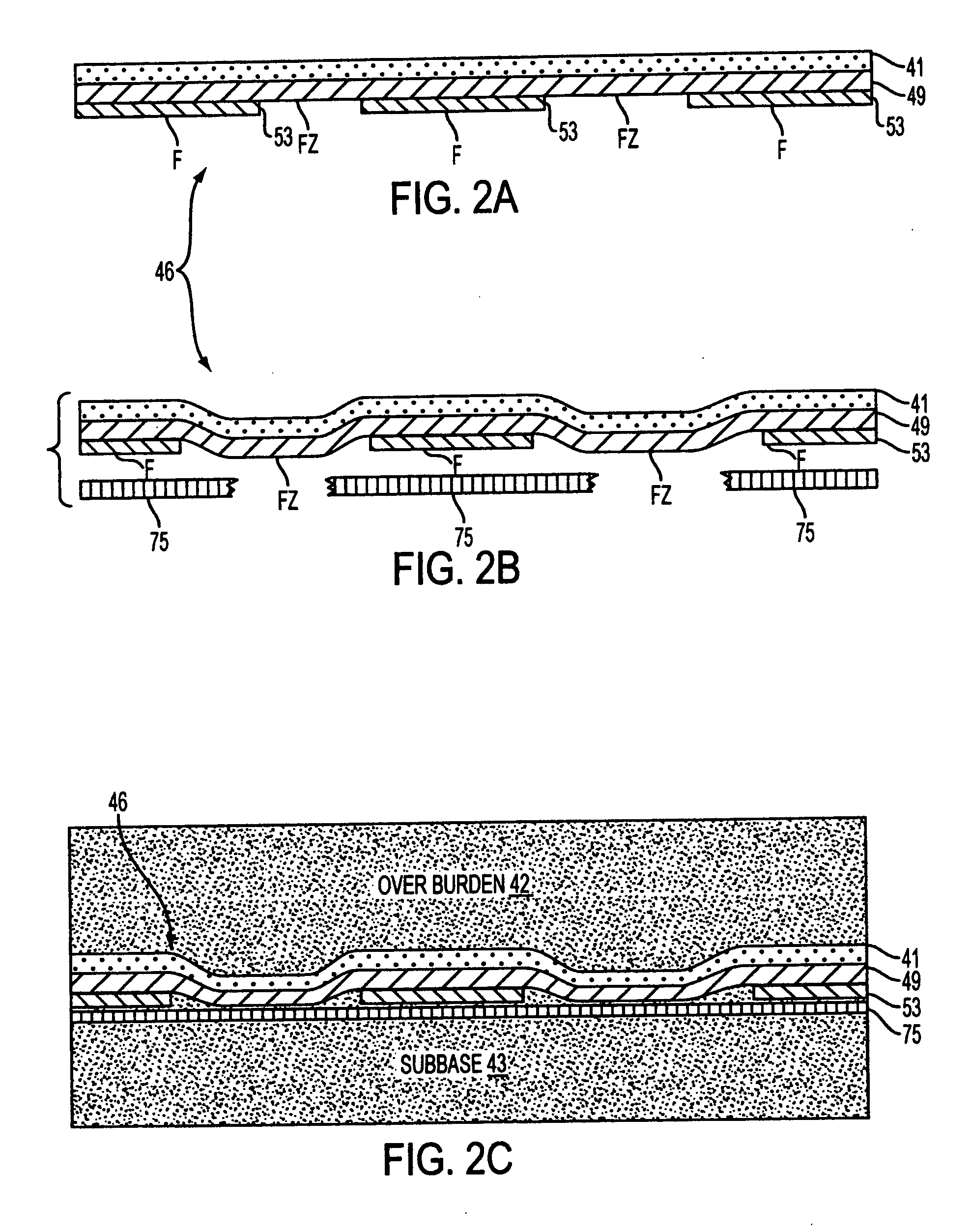
[0050] The present invention includes methods for designing and using its myriad embodiments. Thus, any combination of flow zones, friction zones and anchor zones can be combined to form a drainage structure of desired drainage capacity and resistance to movement on a g...


PUM


Abstract

Numerous permutations of high-friction void-maintaining membrane laminates are provided. Laminates of the invention are particularly useful for providing high performance drainage within installations having a high slope component. Void-maintaining laminates of the invention comprise flow zones of void spaces which are typically interconnected, and constructed and arranged so that the flow zones provide desirable paths for the egress of drainage fluids. The laminates advantageously include also high-friction zones which are typically interspersed between the flow zones such that the laminates are useful to provide drainage in installations of high incline angles. Laminates of the present invention provide both desired resistance to movement, that is, increased shear resistance, and flow capacity increases of from 25-100% when compared with conventional laminates.

Description

RELATED APPLICATIONS [0001] Applicant claims priority to U.S. Provisional Application Ser. No. 60 / 460,784, filed Apr. 7, 2003, and to U.S. Provisional Application Ser. No. 60 / 460,147, filed Apr. 4, 2003.FIELD OF THE INVENTION [0002] The present invention relates generally to geonets and geocomposite drainage structures that are constructed and arranged to possess high resistance to unwanted movement while in place. The high-friction elements or portions of the laminates, friction zones, anchor zones and fluid transmission zones (“flow zones”) of structures of the invention advantageously can be constructed and arranged such that desired fluid flow paths or patterns are provided through the fluid transmission zones of the laminates while portions of the laminate are dedicated to maintaining a high resistance to movement of the laminate with respect to adjacent membranes and with respect to the soils in which the laminates are positioned. Structures of the invention are therefore part...

Claims


Application Information

Patent Timeline
Patent Type & Authority Applications(United States)
IPC IPC(8): E02B11/00
CPCE02B11/005
Inventor IANNIELLO, PETER J.
Owner IANNIELLO PETER J
Why Eureka
Try Eureka