Burner with high-efficiency atomization

a high-efficiency, atomization technology, applied in the field of combustion, can solve the problems of fuel flowing backward into the oxygen or air conduit, unintended combustion or even an explosion, and pressure dropping,

Active Publication Date: 2005-02-03
MG IND +1
View PDF13 Cites 21 Cited by
  • Summary
  • Abstract
  • Description
  • Claims
  • Application Information

AI Technical Summary

Benefits of technology

[0016] The invention has the further object of providing a burner nozzle which effectively mixes

Problems solved by technology

Internal mix nozzles have the disadvantage that the structure that is useful for creating a tortuous path also creates resistance to fluid flow, and thus inherently induces a pressure drop.
Another disadvantage of an internal mix nozzle is that fuel may flow backward into the oxygen or air conduit, or oxygen or air may flow backward into the fuel conduit, due to differences in pressure while in operation or from loss of

Method used


Image

  • Burner with high-efficiency atomization
  • Burner with high-efficiency atomization
  • Burner with high-efficiency atomization

Examples


Embodiment Construction

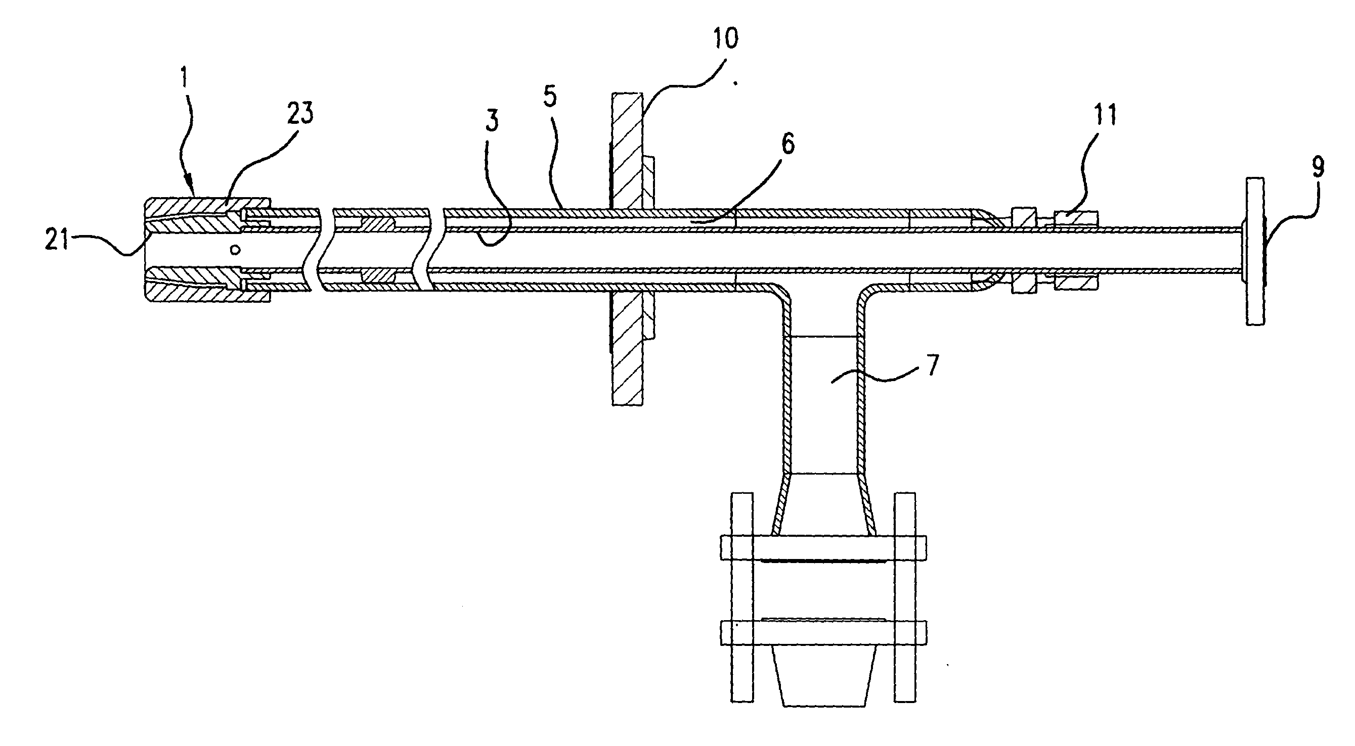
[0023]FIG. 1 provides a cross-sectional view of a burner made according to the present invention. The burner includes nozzle 1, the structure of which will be described in more detail below. The nozzle includes an inner piece 21 and an outer piece 23. The inner and outer pieces are mounted, respectively, to two concentric pipes, namely inner pipe 3, which defines a conduit for fuel flow, and outer pipe 5 which, together with inner pipe 3, defines an annular region 6 within which the atomizing media (usually air and / or oxygen) can flow. Preferably, the inner and outer pieces are screwed onto the respective pipes. In general, the inner and outer pipes are longer than the length of the nozzle. Moreover, as indicated in FIG. 1, the inner and outer pipes may be many times longer than the length of the nozzle.

[0024] Air or oxygen enters the system through conduit 7, which is in fluid communication with the annular region 6. Fuel is preferably introduced into inner pipe 3 at or near end p...


PUM


Abstract

A burner has a nozzle formed of generally concentric inner and outer pieces. The inner piece defines a fuel conduit, and the outer piece defines an annular gas conduit which tapers down towards the outlet end of the nozzle. The inner piece has a rounded edge near the outlet end. The inner piece is longitudinally translatable, within a limited range of movement, relative to the outer piece, and can be locked into a desired position. The nozzle promotes efficient mixing of fuel and air (or oxygen) outside the burner. The stream of air creates a partial vacuum in the vicinity of the outlet end, serving to draw fuel out of the fuel conduit. Longitudinal adjustment of the inner piece allows the shape of the flame to be optimized. The burner can be used with virtually any fuel that can be provided in fluid form, whether solid, liquid or gas.

Description

BACKGROUND OF THE INVENTION [0001] The present invention relates to the field of combustion, and provides a device which is capable of efficiently atomizing both gaseous and liquid media of varying viscosities, as well as fine fluidized solids. [0002] The present invention provides a novel structure for improving the efficiency of combustion. Combustion efficiency is determined, in large part, by the thoroughness of the mixing of the fuel with oxygen or air. The burner of the present invention has a nozzle configuration that promotes such efficient mixing. In particular, the novel burner promotes thorough combustion due to the recirculation of gas by molecular entrainment outside the burner, due to the structure of the burner nozzle, and also due to the internal recirculation of gases within the tapered flow cone of the gas stream. [0003] The nozzles used in the prior art can be categorized as “internal mix” or “external mix” nozzles. An internal mix nozzle is one in which the fuel ...

Claims


Application Information

Patent Timeline
IPC IPC(8): F23D11/10F23D14/22F23D14/32F23D14/48
CPCF23D11/108F23D14/22Y02E20/344F23D14/48F23D2900/14481F23D14/32
Inventor MASI, RICHARD R.THIBOU, MICHAEL R.SCHARTEL, TERRY R.
Owner MG IND
Why Eureka
Try Eureka