Vision catheter

a catheter and vision technology, applied in the field of medical devices, can solve the problems of large large area, and complex movement type, and achieve the effects of reducing the size of the camera, facilitating assembly, and enhancing the vision field at the distal end

Inactive Publication Date: 2005-02-03
SCI MED LIFE SYST +1
View PDF15 Cites 91 Cited by
  • Summary
  • Abstract
  • Description
  • Claims
  • Application Information

AI Technical Summary

Benefits of technology

[0006] In an embodiment utilizing an electrical coil, a metal-type ring or object encases the distal end and is contained in a housing with the electrical coil for vibrating the distal end in a controlled manner. This produces a scanning effect in that as the distal end moves, the field of vision at the distal end effectively increases. In alternate embodiments, the housing may contain other technologies for creating the movement, such as piezoelectric crystals, MEMS, etc. An objective lens or a series of lenses is placed in front of the distal end to magnify the image. A focusing screw mechanism is incorporated so that the image can be focused. At the proximal end, an imaging device such as a CCD, CMOS, pin hole, or photo diode camera is positioned so as to capture and transfer the image to either a processor or a computer that is able to store or display the image. A light processing box is located between the camera and the proximal end, which provides the source for the light that illuminates the imaged area.
[0007] It will be appreciated that the vision catheter of the present invention includes components that are widely available and that can easily be assembled. The simple design thus allows for the production of catheters that are relatively inexpensive and disposable and which have imaging capabilities while still remaining relatively small in diameter.

Problems solved by technology

One drawback of this alternative is that such cameras are relatively large in size, in comparison to the dimensions needed for certain surgical procedures.
Another issue with either the semiconductor-type camera or the bundle of fibers, is that the ability to see a larger area requires moving the camera or the bundle of fibers.
This type of movement is relatively complex to implement, and requires even more area.
Furthermore, while endoscopes are a proven technology, they are relatively complex and expensive to manufacture.

Method used


Image

  • Vision catheter
  • Vision catheter
  • Vision catheter

Examples


Embodiment Construction

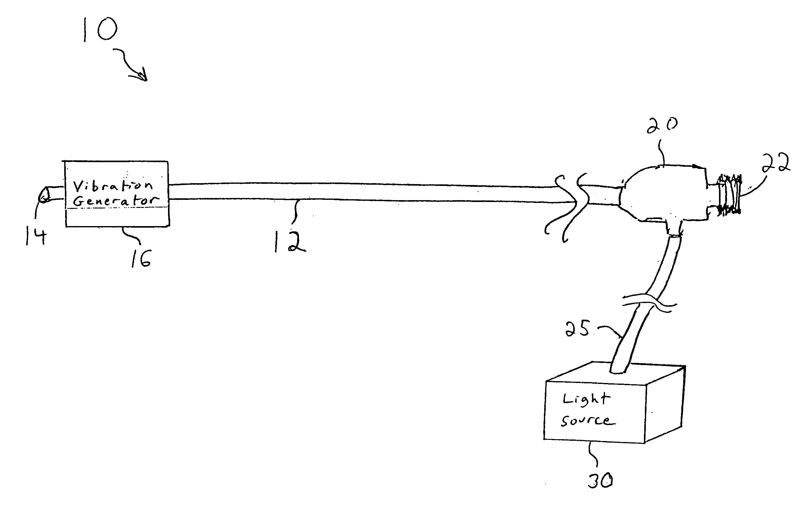
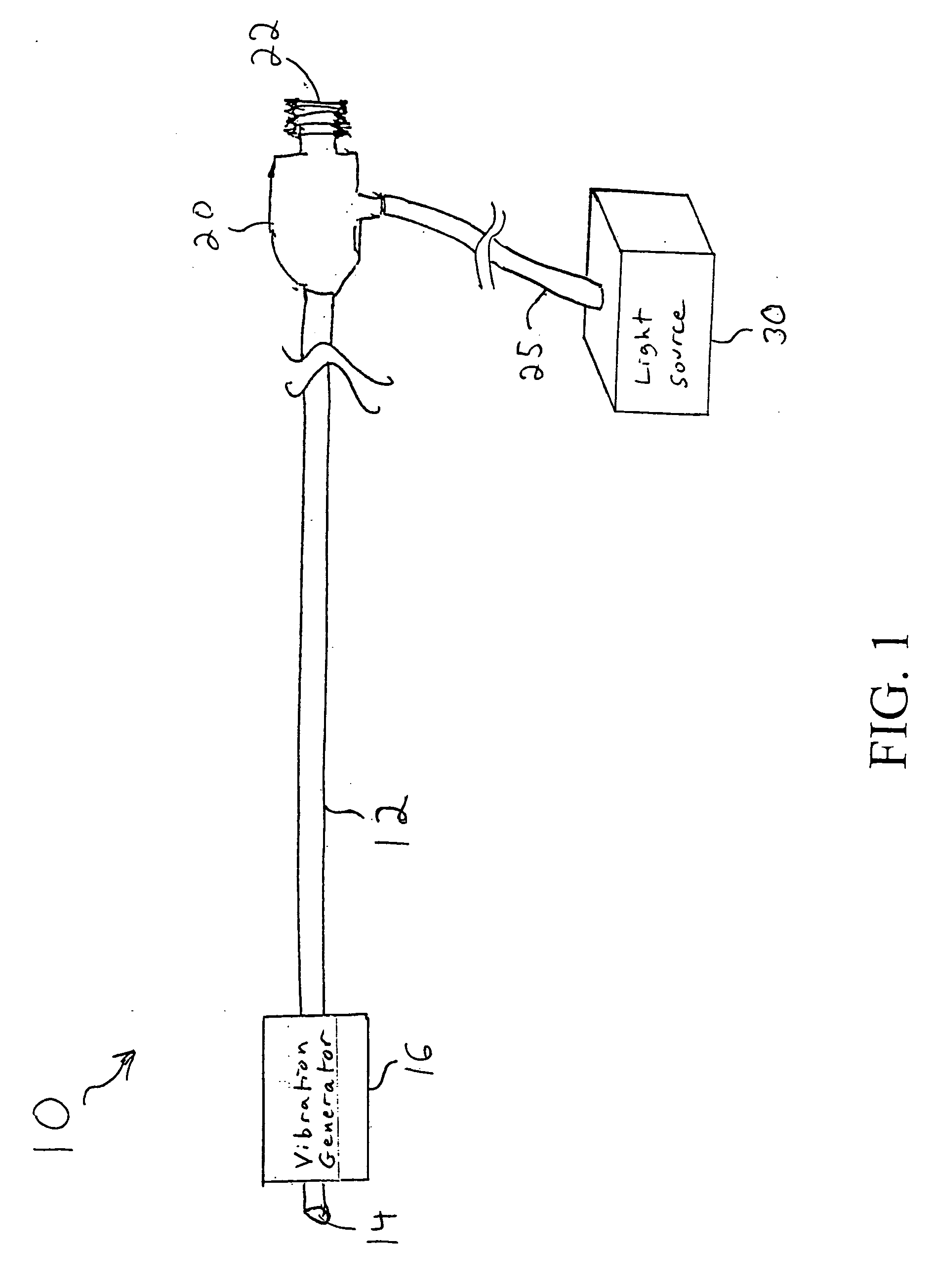
[0011]FIG. 1 is a diagram of a vision catheter 10 formed in accordance with the present invention. The vision catheter 10 includes a flexible imaging cable 12 having a polished distal end 14. In one embodiment, the flexible imaging cable 12 may include a group of standard clad optical fibers. In general, the optical fibers will include one or more imaging fibers and one or more illumination fibers. The imaging fibers transmit image information detected at the distal end 14 of the imaging cable 12. The illumination fibers are coupled to a light source so as to provide illumination at the distal end 14 of the imaging cable 12.

[0012] The vision catheter 10 also includes a vibration generator 16. In accordance with the present invention, the vibration generator 16 vibrates the distal end 14 of the imaging cable 12. This essentially produces a scanning effect in that as the distal end 14 moves, the field of view that is sensed by the distal end 14 effectively increases. As will be descr...


PUM


Abstract

A catheter with a small optical fiber or bundle of fibers includes a scanning mechanism constructed with the use of any vibration capable component. Magnetic, piezoelectric or other mechanisms are used to vibrate the end of the fiber and thus create a scanning effect which extends the field of view. This configuration can be used in a catheter with a relatively small diameter. A glass lens or lenses placed in front of the fiber focuses and magnifies the image. A CCD, CMOS, or photodiode camera at the proximal end of the fiber captures the image and transfers it to a computer or processor. A light splitter coupled to a light source provides light through an illumination fiber. The resulting vision catheter is relatively inexpensive and disposable.

Description

FIELD OF THE INVENTION [0001] The present invention relates to medical devices, and in particular to a catheter with imaging capabilities. BACKGROUND OF THE INVENTION [0002] An endoscope is a type of catheter that has imaging capabilities so as to be able to provide images of an internal body cavity of a patient. Most minimally invasive surgical procedures performed in the GI tract or other internal body cavities are accomplished with the aid of an endoscope. A typical endoscope has an illumination channel and an imaging channel, both of which may be made of a bundle of optical fibers. The illumination channel is coupled to a light source to illuminate an internal body cavity of a patient, and the imaging channel transmits an image created by a lens at the distal end of the scope to a connected camera unit or display device. [0003] As an alternative to an imaging channel made of a bundle of optical fibers, a semiconductor-type camera can also be attached onto the distal tip. One dra...

Claims


Application Information

Patent Timeline
Patent Type & Authority Applications(United States)
IPC IPC(8): A61B1/005A61B1/04A61B1/07
CPCA61B1/0008A61B1/00096A61B1/00165A61B1/07A61B1/00183A61B1/0051A61B1/00172
Inventor CHIN, YEMBARBATO, LOUIS J.HAMM, MARK A.
Owner SCI MED LIFE SYST
Why Eureka
Try Eureka