Patient cable for medical measurements

a technology for medical measurements and cables, applied in the field of patient cables or electrode lead wires, can solve the problem of insufficient resistance of the second element for this purpose, and achieve the effect of effectively eliminating the risk of thermal injuries

Inactive Publication Date: 2005-02-03
GE HEALTHCARE FINLAND +1
View PDF7 Cites 19 Cited by
  • Summary
  • Abstract
  • Description
  • Claims
  • Application Information

AI Technical Summary

Benefits of technology

[0014] The objective of the present invention is to bring about a novel patient cable suitable for use in MRI environments, Which effecti

Problems solved by technology

The resistance of the second element is clearly insufficient for this

Method used


Image

  • Patient cable for medical measurements
  • Patient cable for medical measurements

Examples


Embodiment Construction

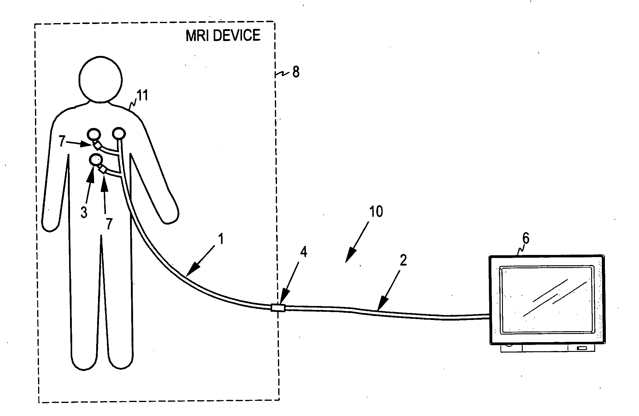
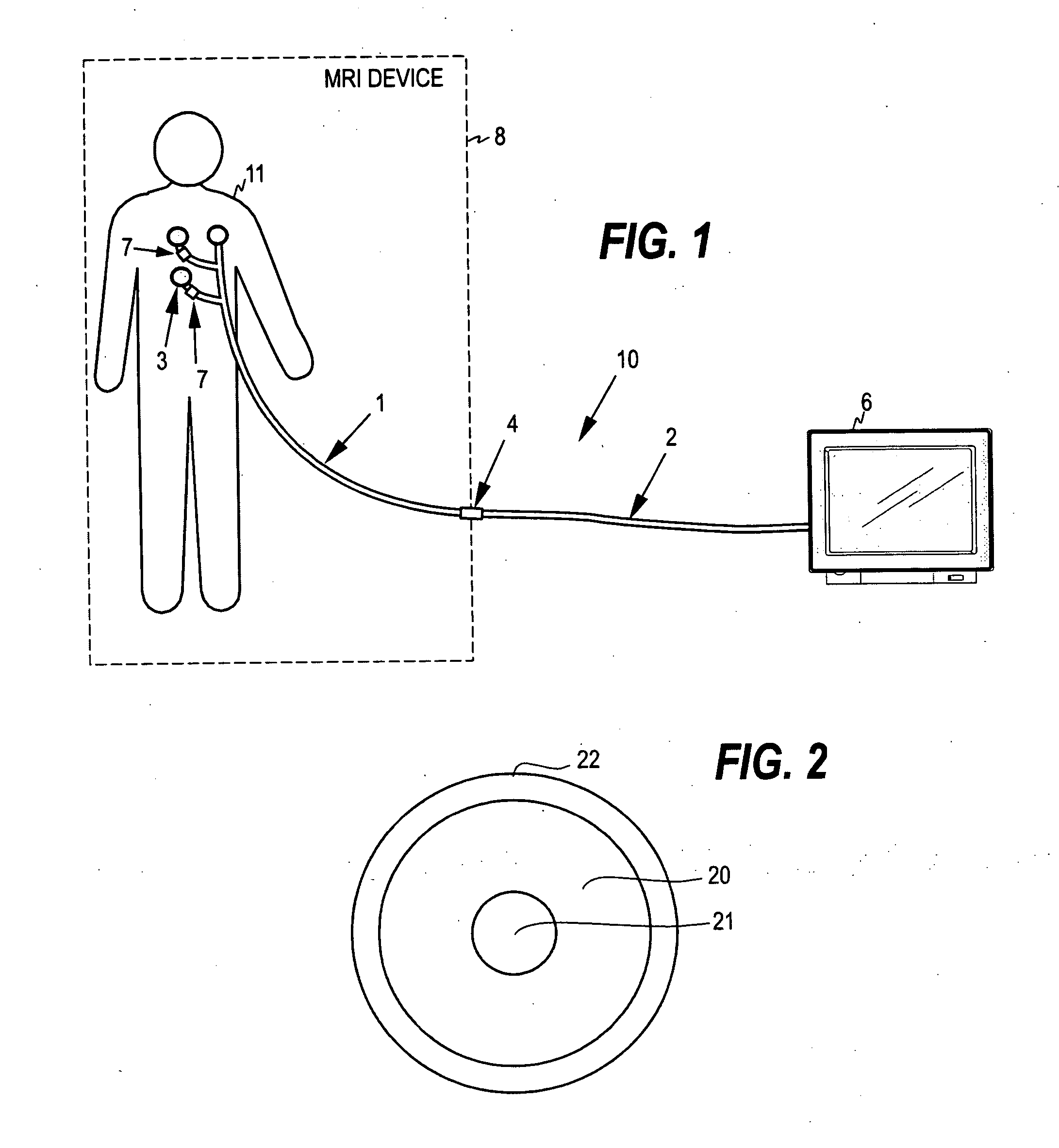
[0024]FIG. 1 illustrates the basic principle of a patient cable 10 according to the invention. The cable comprises two successive elements: a first cable element 1 that extends from patient 11 towards a monitoring device 6, and a second cable element 2 that connects the first cable element to the monitoring device located farther away from the patient lying inside an MRI device 8.

[0025] The first cable element is at its first end connected to electrodes 3 attached on the skin of the patient. The length of the first cable element is dimensioned so that the first cable element forms substantially the part of the whole cable 10 that is inside the MRI device. The first cable element is at its second end connected to the first end of the second cable element 2. The mating connectors of the first and second cable elements are denoted with reference numeral 4. The second end of the second element is connected to the monitoring device that is apart from the MRI device. The said second end ...


PUM


Abstract

The invention relates to a patient cable for medical measurements performed in connection with Magnetic Resonance Imaging (MRI). In order to eliminate the risk of thermal injuries without compromising the signal-to-noise ratio more than what is required for patient safety, the patient cable comprises two successive cable elements having different resistance characteristics. The second cable element, which is connected by the first cable element to the patient, has a total resistance increased from a normal high-conductivity resistance value of a patient cable to suppress antenna resonances in the second cable element. The first cable element, which is connected to the electrodes on the skin of the patient, has a total resistance substantially greater than that of the second cable element to prevent electromagnetically induced currents from flowing to the patient and to prevent excessive heating of the cable by electromagnetic induction.

Description

FIELD OF THE INVENTION [0001] The present invention relates generally to patient cables or electrode lead wires used in medical measurements for measuring bioelectric signals. More particularly, the present invention relates to patient cables suitable for Magnetic Resonance Imaging (MRI). BACKGROUND OF THE INVENTION [0002] As is known, MRI (Magnetic Resonance Imaging) is a technique used for getting images of a body without the use of X-rays. In MRI, the patient is placed within a rapidly changing magnetic field created by the MRI device. Radio waves are simultaneously transmitted to the patient, and images of the interior of the body are obtained by means of a computer analysis of the radio waves received from the patient. During the imaging, the condition of the patient is constantly monitored. This includes the monitoring of the ECG signal of the patient, for example. [0003] The distance between the electrodes attached on the skin of the patient and the physiological monitoring d...

Claims


Application Information

Patent Timeline
IPC IPC(8): A61B5/055A61B5/308
CPCA61B5/04286A61B5/055A61N2001/086A61N1/3718A61B2562/222A61N1/086A61B5/303
Inventor UUTELA, KIMMOMIETTINEN, SAMINIKLANDER, TAPANIVIRTANEN, JUHA
Owner GE HEALTHCARE FINLAND
Why Eureka
Try Eureka