Integrated vehicle motion control system
- Summary
- Abstract
- Description
- Claims
- Application Information
AI Technical Summary
Benefits of technology
Problems solved by technology
Method used
Image

Examples
Embodiment Construction
An exemplary embodiment of the invention will be described in detail with reference to the accompanying drawings.
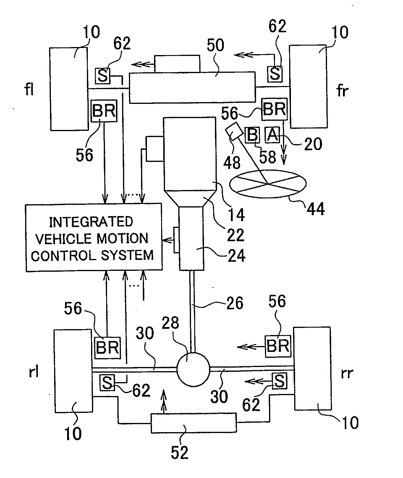
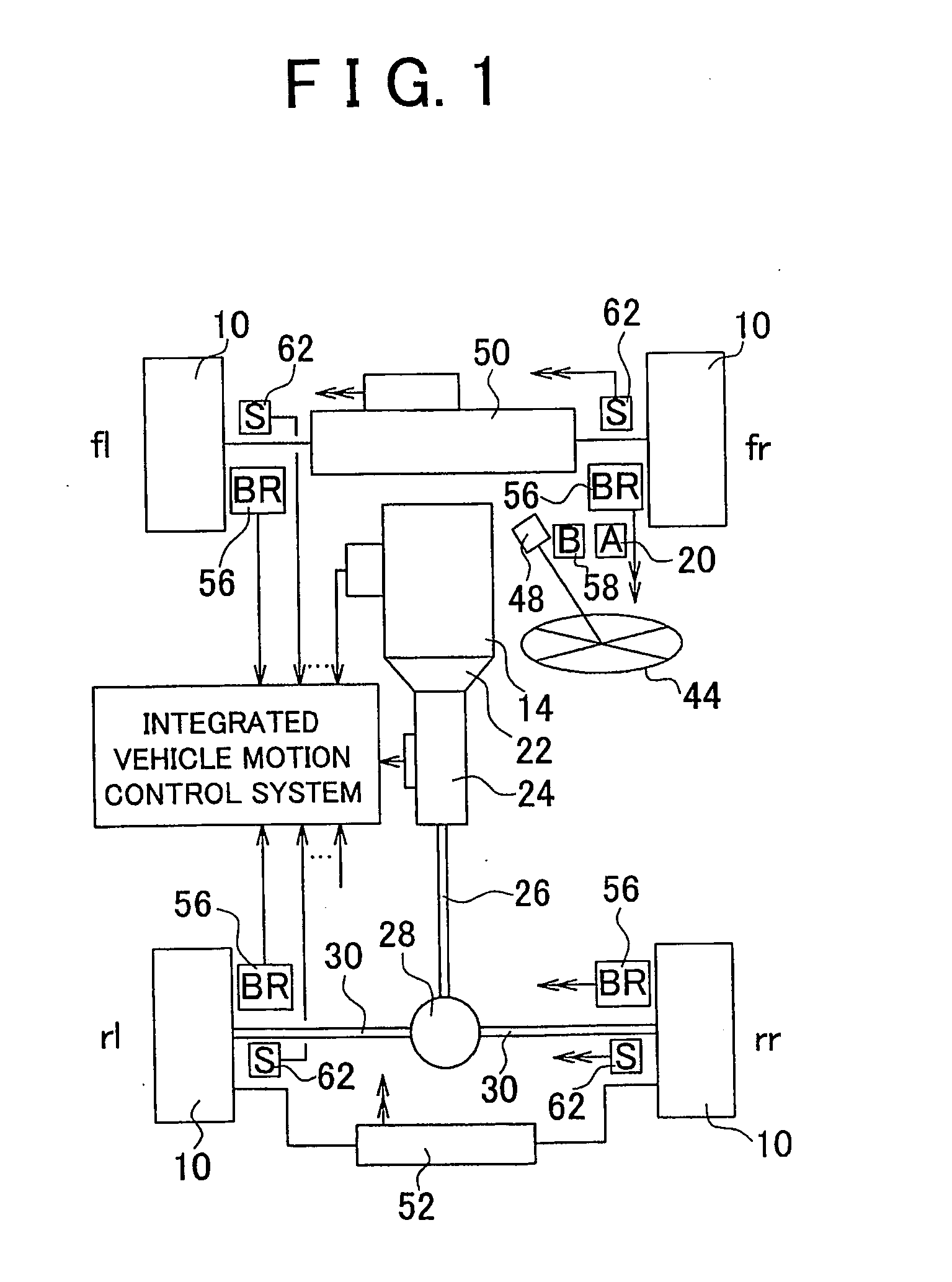
FIG. 1 is a plan view schematically showing a motor vehicle on which an integrated vehicle motion control system according to one exemplary embodiment of the invention is installed. The integrated vehicle motion control system will be hereinafter simply referred to as “motion control system”.
The vehicle of FIG. 1 includes front-left, front-right, rear-left and rear-right wheels 10. In FIG. 1, “fl” denotes a front-left wheel, “fr” denotes a front-right wheel, “rl” denotes a rear-left wheel, and “rr” denotes a rear-right wheel. The vehicle also includes an engine (internal combustion engine) 14 as a driving power source. The operating state of the engine 14 is electrically controlled depending upon an amount or degree by which an accelerator pedal (as one example of an acceleration operating member) is operated by a driver of the vehicle. The operating state of the engi...
PUM
 Abstract
Description
Claims
Application Information
 - Generate Ideas
- Intellectual Property
- Life Sciences
- Materials
- Tech Scout
- Unparalleled Data Quality
- Higher Quality Content
- 60% Fewer Hallucinations
Browse by: Latest US Patents, China's latest patents, Technical Efficacy Thesaurus, Application Domain, Technology Topic, Popular Technical Reports.
© 2025 PatSnap. All rights reserved.Legal|Privacy policy|Modern Slavery Act Transparency Statement|Sitemap|About US| Contact US: help@patsnap.com