Auger type ice making machine

Inactive Publication Date: 2005-02-10
HOSHIZAKI ELECTRIC CO LTD
View PDF5 Cites 11 Cited by
  • Summary
  • Abstract
  • Description
  • Claims
  • Application Information

AI Technical Summary

Benefits of technology

[0006] The present invention has been made in view of the problems mentioned above, and it is therefore an object of the present invention to p

Problems solved by technology

When overcooling occurs in such an auger type ice making machine, however, a large load is applied to an ice making mechanism portion, which may lead to such defects as cylinder freeze-up due to ice clogging, noise generation, abnormal wear of bearings, breakage of the auger or a geared motor, etc.
As a result, the refrigerant pressure and the evaporation temperature on the low pressure side rise, thereby reducing the ice making capacity.
However, in the initial stage of overcooling, it is often the case that the rpm of the

Method used


Image

  • Auger type ice making machine
  • Auger type ice making machine
  • Auger type ice making machine

Examples


Embodiment Construction

[0012] Hereinafter, an embodiment of the present invention is described with reference to the accompanying drawings.

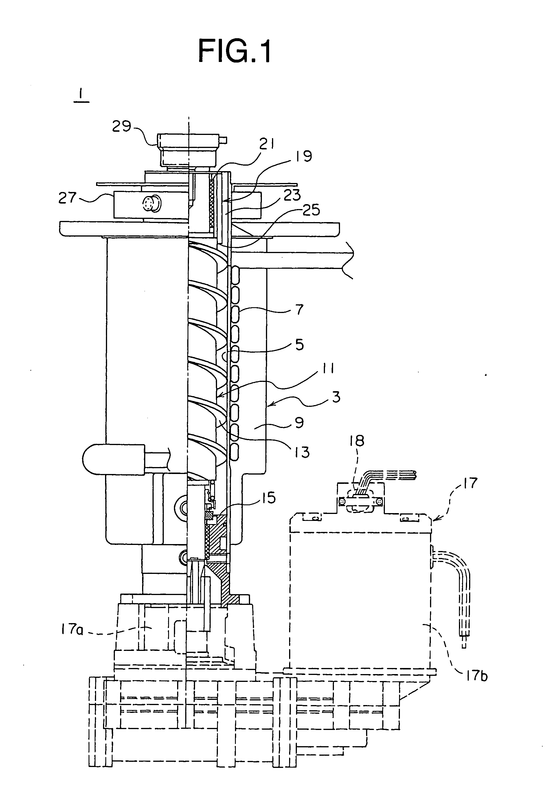
[0013]FIG. 1 shows a longitudinal section of an ice making mechanism portion of an auger type ice making machine according to the embodiment of the present invention. In an ice making mechanism portion 3 of an auger type ice making machine 1, there is provided a cylinder 5 formed of metal. A cooling pipe 7 is wound in a spiral fashion around an outer peripheral surface of the cylinder 5. The cooling pipe 7 functions as an evaporator which constitutes a component of a refrigerant circuit described later. The cylinder 5 and the cooling pipe 7 are covered with a heat insulating material 9. Further, an auger 11 is rotatably arranged inside the cylinder 5. The auger 11 has a helical blade 13 formed on its outer peripheral surface. A lower part of the auger 11 is supported by a bearing 15 arranged at the lower end of the cylinder 5. Further, the lower end of the auger 11 is...


PUM


Abstract

An auger type ice making machine is provided with a control unit for causing a hot gas valve to open and for causing a heater disposed in the vicinity of ice compression passages to perform heating for a time period longer than the opening period of the hot gas valve, in accordance with a detection result from a rotation detecting sensor which detects rotation of a motor rotating an auger. The opening period of the hot gas valve and the heating period of the heater consist of, respectively: a basic opening period and a basic heating period, each corresponding to a time period during which the rpm of the auger is not higher than a threshold value, and an additional opening period and an additional heating period which are respectively added to the basic opening period and the basic heating period and begin at the time when the auger rpm exceeds the threshold value.

Description

BACKGROUND OF THE INVENTION [0001] 1. Field of the Invention [0002] The present invention relates to an auger type ice making machine. [0003] 2. Description of the Related Art [0004] In an auger type ice making machine, ice-making water supplied into a cylinder is cooled and frozen to form a layer of ice on the inner peripheral surface of the cylinder, and the ice thus formed is scraped off by rotating an auger in the cylinder to provide sorbet-like ice, which is then further compressed to produce suitable particulate ice. When overcooling occurs in such an auger type ice making machine, however, a large load is applied to an ice making mechanism portion, which may lead to such defects as cylinder freeze-up due to ice clogging, noise generation, abnormal wear of bearings, breakage of the auger or a geared motor, etc. In view of this, conventionally, there exists a technique for suppressing the ice making capacity to an optimal state (see, for example, JP 2003-42610 A). That is, high...

Claims


Application Information

Patent Timeline
IPC IPC(8): F25C1/14F25C5/08F25C5/10
CPCF25C1/147F25C5/10F25C5/08F25C5/142
Inventor KUROYANAGI, MASAYUKI
Owner HOSHIZAKI ELECTRIC CO LTD
Why Eureka
Try Eureka