Heating/cooling system for indwelling heat exchange catheter

a heat exchange catheter and indwelling technology, applied in the direction of domestic cooling devices, lighting and heating devices, contraceptives, etc., can solve the problems that single purpose heat exchange catheters, calif., and calif. can be less optimally used

Inactive Publication Date: 2005-02-10
ZOLL CIRCULATION
View PDF15 Cites 47 Cited by
  • Summary
  • Abstract
  • Description
  • Claims
  • Application Information

AI Technical Summary

Benefits of technology

to still further address one or mor

Problems solved by technology

However, single purpose heat exchange catheters such as are made by Innercool Therapies of Sa

Method used


Image

  • Heating/cooling system for indwelling heat exchange catheter
  • Heating/cooling system for indwelling heat exchange catheter
  • Heating/cooling system for indwelling heat exchange catheter

Examples


Embodiment Construction

Description of the Heating / Cooling System

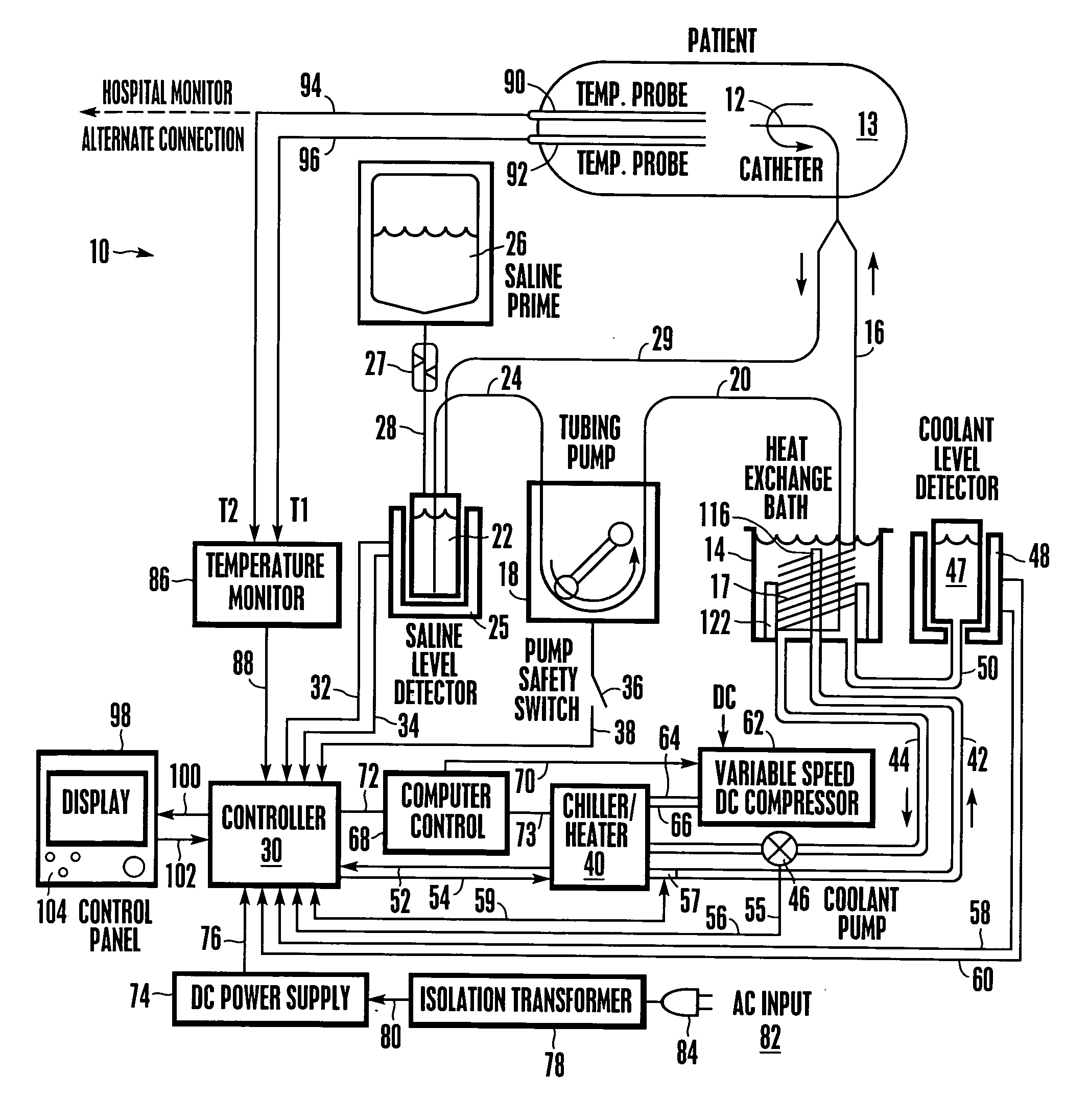
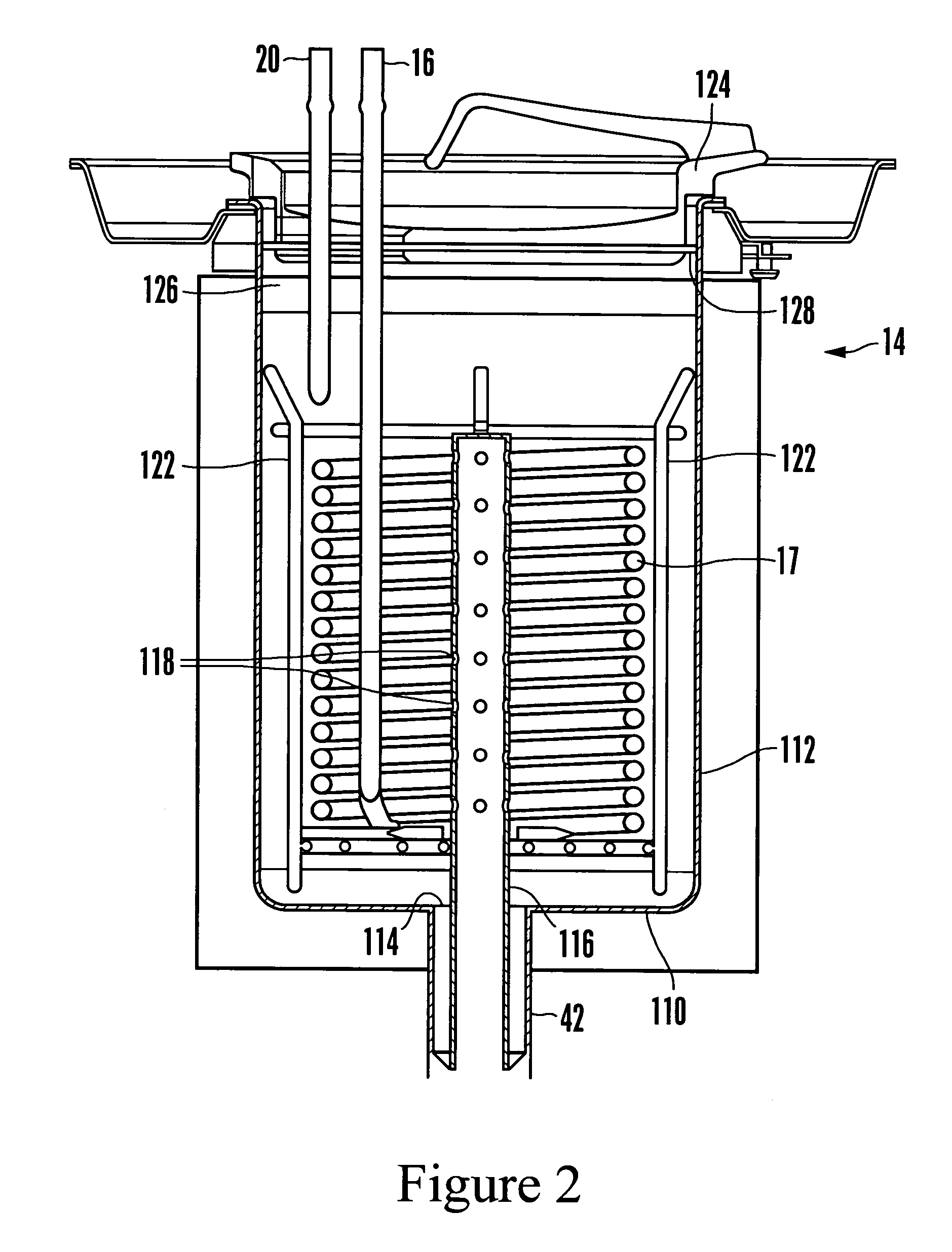
Referring initially to FIG. 1, a patient heating / cooling system is shown and generally designated 10. As shown, the system 10 includes three separate fluid circuits: a saline circuit (also referred to as the working fluid circuit), a water glycol circuit (also referred to as the heating / cooling fluid circuit), and a refrigerant circuit (also referred to as the refrigerating fluid circuit.)

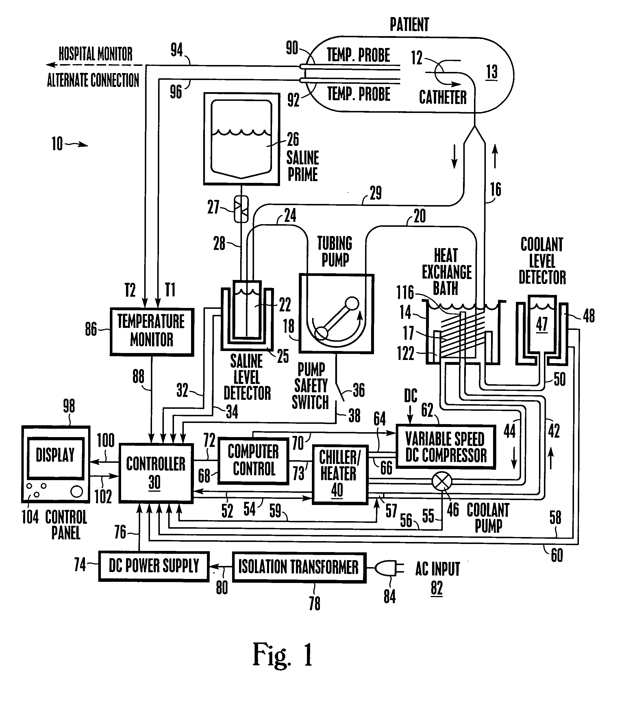
Taking the saline circuit first, an indwelling heat exchange catheter 12 that can be inserted into a patient 13 during an operation is connected to a heat exchange bath 14 by a saline supply line 16. The supply line 16 is connected to a coiled or helical heat exchange tube 17 that is immersed in the bath 14 fluid to exchange heat therewith. In turn, the heat exchange tube 17 is connected to a peristaltic tubing saline pump 18 by fluid line 20. Preferably, the saline pump 18 draws saline from a saline reservoir 22 via fluid line 24. As shown, the saline ...


PUM


Abstract

A cooling system for an indwelling heat exchange catheter includes a heat exchange bath that is configured to receive a conduit that carries saline to and from the catheter. A heating/cooling fluid is in the bath and exchanges heat with the saline. The heating/cooling fluid flows through a heat exchanger that includes a refrigerant and two variable speed DC compressor for removing heat from the refrigerant. A gear pump circulates the working fluid to and from the catheter and is removably engaged with a pump support platform.

Description

BACKGROUND OF THE INVENTION 1. Field of the Invention The present invention relates generally to methods and apparatus for exchanging heat with the body of a patient. 2. Description of the Related Art It has been discovered that the medical outcome for a patient suffering from severe brain trauma or from ischemia caused by stroke or heart attack is improved if the patient is cooled below normal body temperature (37° C.). Furthermore, it is also accepted that for such patients, it is important to prevent hyperthermia (fever) even if it is decided not to induce hypothermia. Moreover, in certain applications such as post-CABG surgery, it might be desirable to rewarm a hypothermic patient. As recognized by the present invention, the above-mentioned advantages in regulating temperature can be realized by cooling or heating the patient's entire body. Moreover, the present invention understands that since many patients already are intubated with central venous catheters for other clin...

Claims


Application Information

Patent Timeline
IPC IPC(8): A61F7/00A61F7/12F25D17/02
CPCA61F7/0085A61F7/12A61F2007/0054A61F2007/0093F25D17/02A61F2007/126F25B2400/01F25B2600/0253F25B2700/1351A61F2007/0096F04C2/18F04C15/0069F04C29/0064F04D13/024F04D29/606
Inventor NODA, WAYNESTELEA, STELICA
Owner ZOLL CIRCULATION
Why Eureka
Try Eureka