Fuel supply control system for engine

Inactive Publication Date: 2005-02-10
HONDA MOTOR CO LTD
View PDF5 Cites 10 Cited by
  • Summary
  • Abstract
  • Description
  • Claims
  • Application Information

AI Technical Summary

Benefits of technology

[0006] Accordingly, it is an object of the present invention to provide a fuel supply control system for an engine, wherein the transmission of a negative pressure from a negative pressure generating section to a negative pressure conduit is not obs

Problems solved by technology

Especially, a general-purpose engine may be largely inclin

Method used


Image

  • Fuel supply control system for engine
  • Fuel supply control system for engine
  • Fuel supply control system for engine

Examples


first embodiment

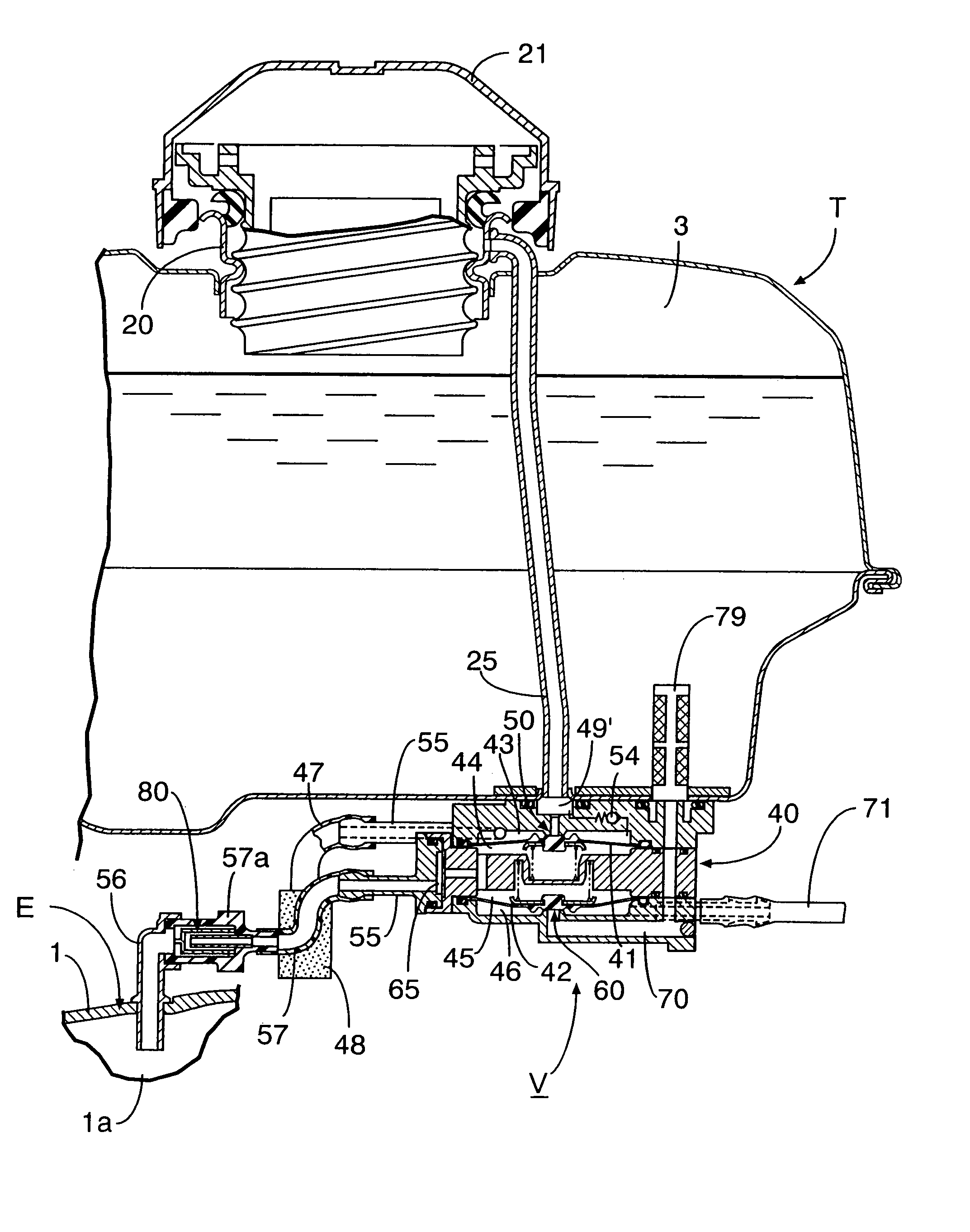
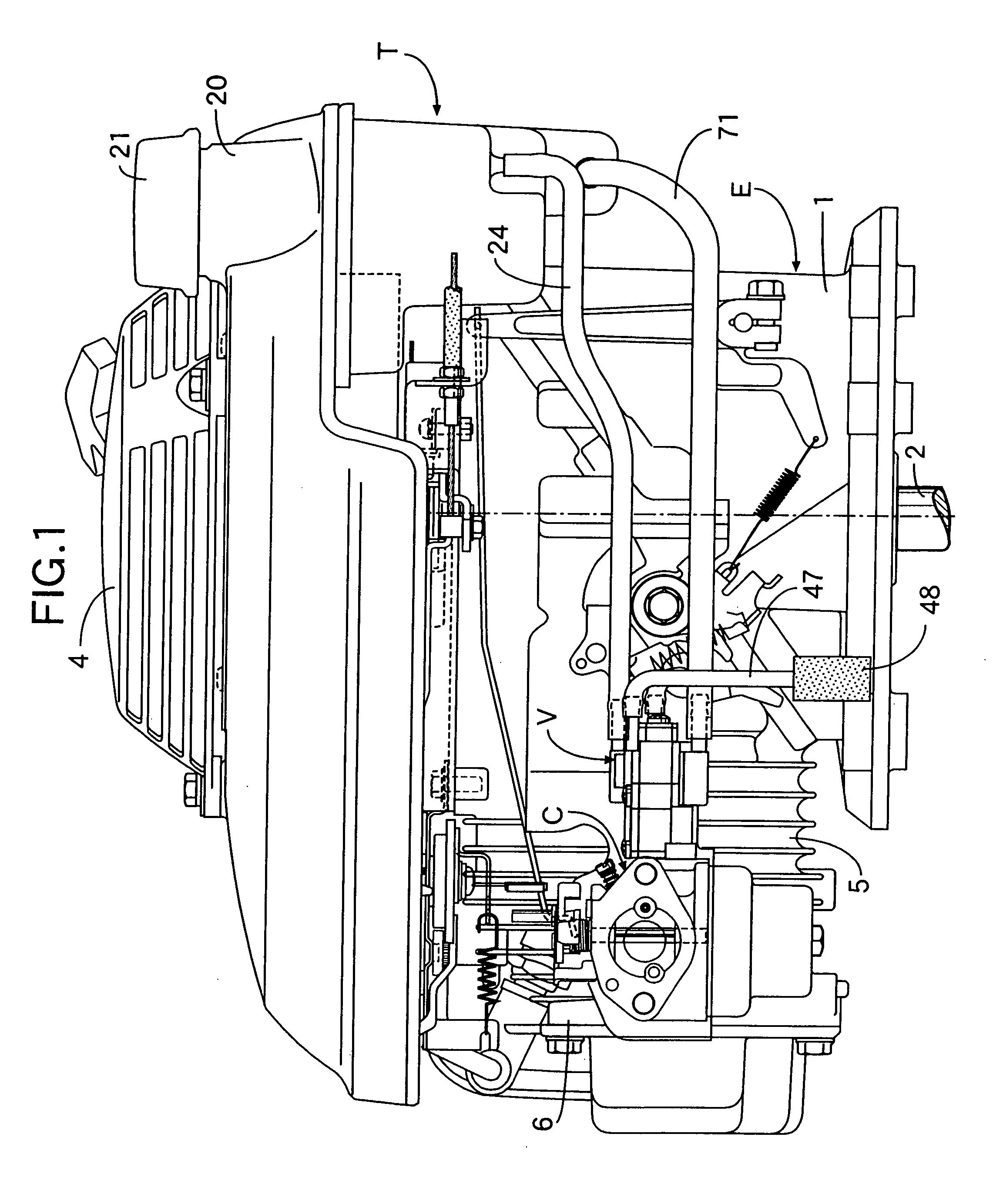
[0032] the present invention shown in FIGS. 1 to 11 will be described first. In FIGS. 1 and 2, reference character E denotes a general-purpose engine of a 4-cycle vertical type. A crankshaft 2 supported in a crankcase 1 of the engine E is disposed vertically with its output end protruding downward below the crankcase 1. A fuel tank T and a recoil starter 4 are mounted to an upper portion of the crankcase 1.

[0033] A cylinder block 5 having a cylinder axis disposed horizontally is connected to one side of the crankcase 1, and a carburetor C is mounted to one side of a cylinder head 6 coupled to a tip end of the cylinder block 5.

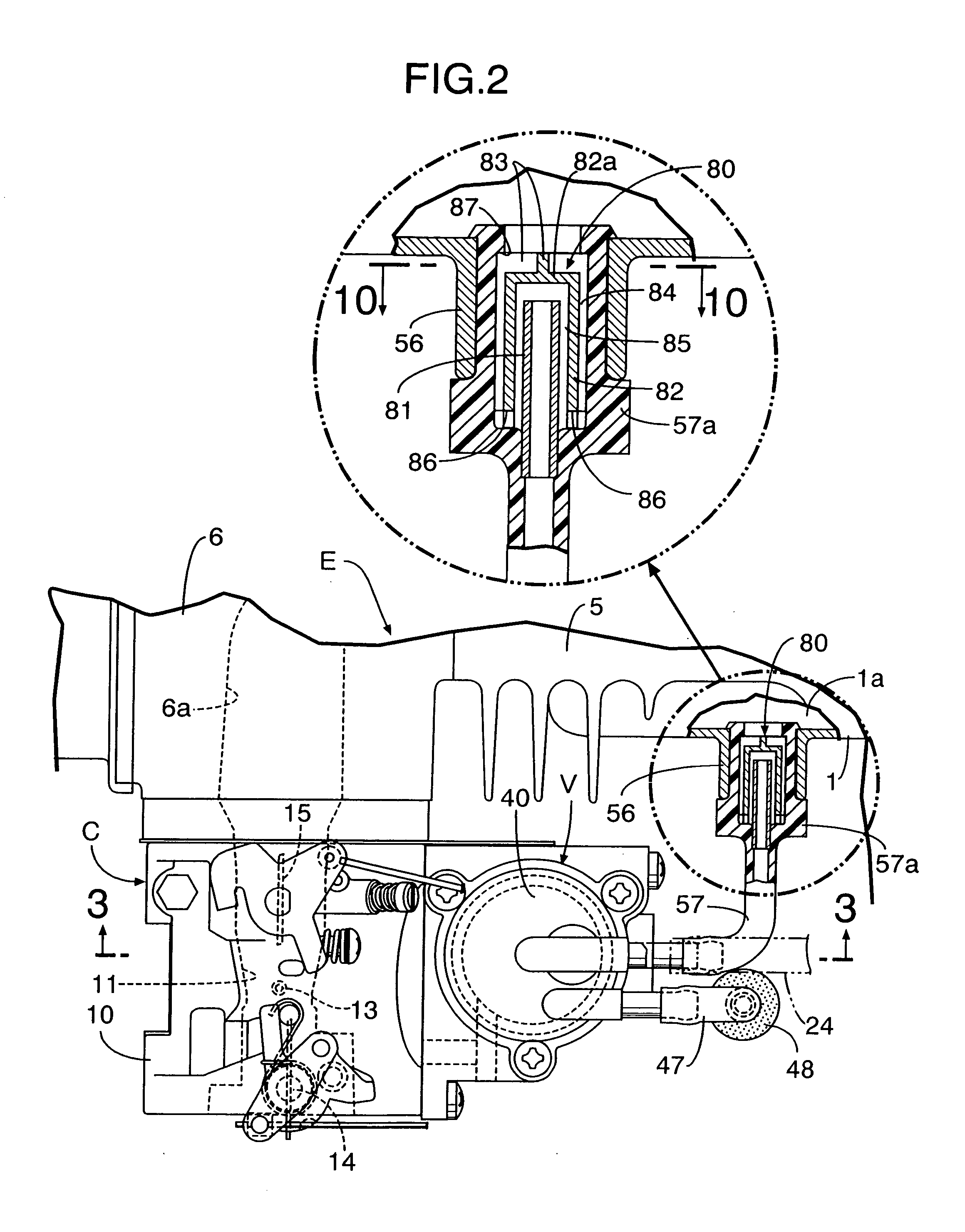
[0034] Referring to FIG. 3, the carburetor C includes a carburetor body 10 having an intake passage 11 leading to an intake port 6a in the cylinder head 6, a float chamber member 12 coupled to a lower surface of the carburetor body 10 and having a float chamber 12a, a fuel nozzle 13 which permits an area below a fuel oil surface in the float chamber 12a to com...

second embodiment

[0075] the present invention shown in FIG. 12 will now be described.

[0076] In a carburetor C, a small fuel chamber 75 is defined in a nozzle-supporting tube 10a of a carburetor body 10 for supporting a fuel nozzle 13, so that a lower end of the fuel nozzle 13 faces the small fuel chamber 75, and a valve tube 76 interconnecting a float chamber 12a and the small fuel chamber 75 is connected to one side of a nozzle support tube 10a.

[0077] On the other hand, in a valve housing of a composite control valve V, a third block 40 as in the first embodiment is not used, and a second diaphragm 42 is clamped between a second block 40b and an outer side of a float chamber member 12 to which the second block 40b is coupled. A piston-shaped second valve member 62 is mounted to the second diaphragm 42 and slidably fitted in the valve tube 76. The second valve member 62 has an axial communication groove 77 provided in an outer peripheral surface of a tip end thereof. A second control valve 60 for o...

third embodiment

[0082] the present invention shown in FIG. 13 will now be described.

[0083] A composite control valve V is mounted to a bottom surface of a float chamber member 12 in a carburetor C. A second valve seat 61 is formed on a lower end face of a nozzle support tube 10a of a carburetor body 10, and a second valve member 62 cooperating with the second valve seat 61 is connected to a second diaphragm 42 through a collar 78. A second control valve 60 for opening the closing the communication between a small fuel chamber 75 in a lower portion of the nozzle support tube 10a and the float chamber 12a is constructed by the second valve member 62 and the second valve seat 61.

[0084] A diaphragm 74 clamped between the second valve member 62 and the collar 78 has an outer peripheral portion clamped between the bottom surface of the float chamber member 12 and a third block 40c of a valve housing 40, whereby the communication between the float chamber 12a and the third block 40c is cut off. However, ...


PUM

PropertyMeasurementUnit
Pressureaaaaaaaaaa

Abstract

In a fuel supply control system for an engine in which a valve housing is provided with a negative pressure working chamber, and a negative pressure responsive-type control valve operable to be opened and closed in response to generation and extinction of a negative pressure in the negative pressure working chamber, the control valve being incorporated into a fuel passage between a fuel tank and a carburetor, the negative pressure working chamber being in communication with a negative pressure generating section in the engine through a negative pressure conduit, an oil flow-out preventing device is provided in a connecting portion for connecting the negative pressure generating section and the negative pressure conduit to each other. The oil flow-out preventing device is adapted to cut off the communication between the negative pressure generating section and the negative pressure conduit by a lubricating oil received from the negative pressure generating section, when the engine is inclined at a given angle or more. Thus, in an operational attitude of the engine, the transmission of the negative pressure from the negative pressure generating section to the negative pressure conduit is not obstructed, and even when the engine is inclined at the given angle or more in an operation-stopped state of the engine, the lubricating oil in the engine can be prevented from flowing out toward the negative pressure conduit.

Description

BACKGROUND OF THE INVENTION [0001] 1. Field of the Invention [0002] The present invention relates to an improvement in a fuel supply control system for an engine, comprising a diaphragm attached to a valve housing to define a negative pressure working chamber, a control valve which is connected to the diaphragm and which is operable to be opened and closed by advancing and returning of the diaphragm due to generation and extinction of a negative pressure in the negative pressure working chamber, the control valve being incorporated into a fuel passage system which provides communication between a portion of a fuel tank below a fuel oil surface and a fuel supply section in the engine, the negative pressure working chamber being in communication with a negative pressure generating section in the engine through a negative pressure conduit. [0003] 2. Description of the Related Art [0004] Such a fuel supply control system for an engine is already known, as disclosed in, for example, Japa...

Claims


Application Information

Patent Timeline
IPC IPC(8): F02M37/00F02M17/04F02M25/08F16K24/00
CPCF02M17/04F02M25/0836Y10S261/68F02M25/089F02M25/0872
Inventor YAMADA, YOSHIKAZU
Owner HONDA MOTOR CO LTD
Why Eureka
Try Eureka