Rotational speed adjustment mechanism of a pneumatic tool

a technology of rotating speed adjustment and pneumatic tools, which is applied in the field of pneumatic tools, can solve the problems of air pressure, difficult to control the precision of the valve stem, and difficulty in manufacturing and processing specially shaped valve stems, and achieves the effects of high precision, simplified rotating speed adjustment mechanisms, and easy manufacturing and processing

Inactive Publication Date: 2005-02-10
CHUANG CHIA CHIUNG
View PDF6 Cites 3 Cited by
  • Summary
  • Abstract
  • Description
  • Claims
  • Application Information

AI Technical Summary

Benefits of technology

[0004] It is therefore a primary object of the present invention to provide a rotational speed adjustment mechanism of a pneumatic tool. The components of the rotational speed adjustment mechanism are simplified and easy to manufacture and process at high precision. Therefore, the quality of the product can be easily maintained.

Problems solved by technology

It is uneasy to manufacture and process the specially shaped valve stem.
Therefore, it is hard to control the precision of the valve stem.
Therefore, when the high pressure air is filled up in the intake passage, the air pressure will lead to leakage of a part of the air.
As a result, the energy is partially wasted.

Method used


Image

  • Rotational speed adjustment mechanism of a pneumatic tool
  • Rotational speed adjustment mechanism of a pneumatic tool
  • Rotational speed adjustment mechanism of a pneumatic tool

Examples


Embodiment Construction

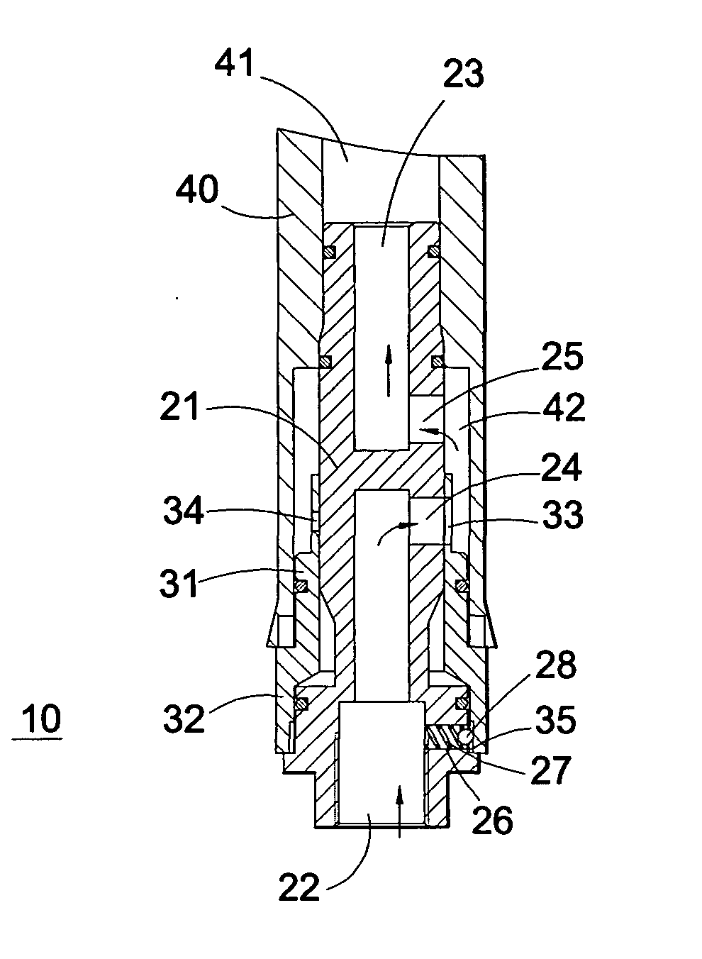
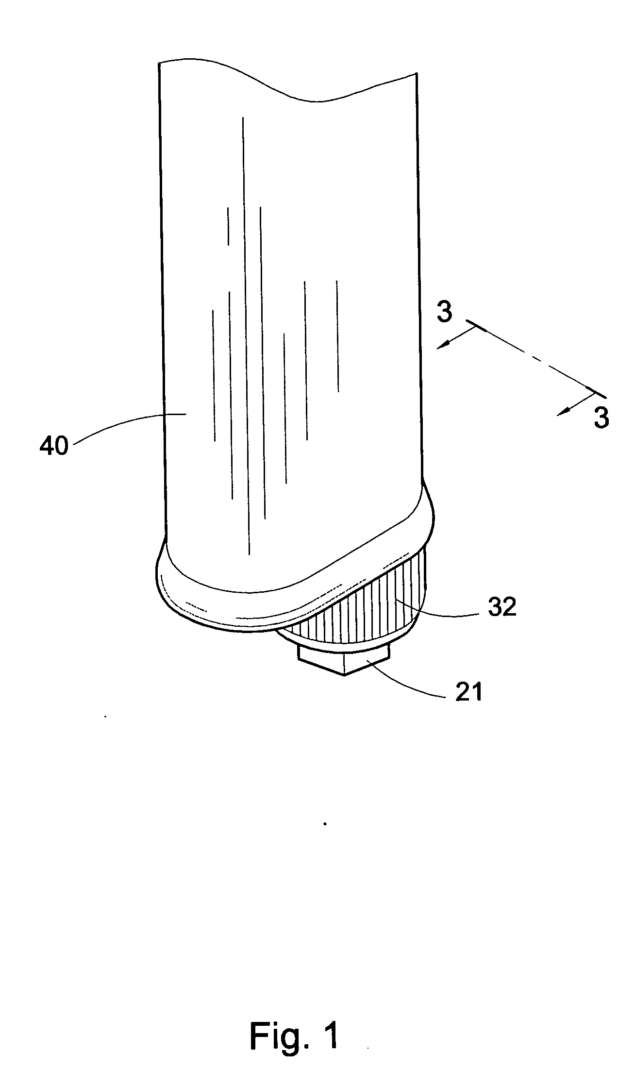
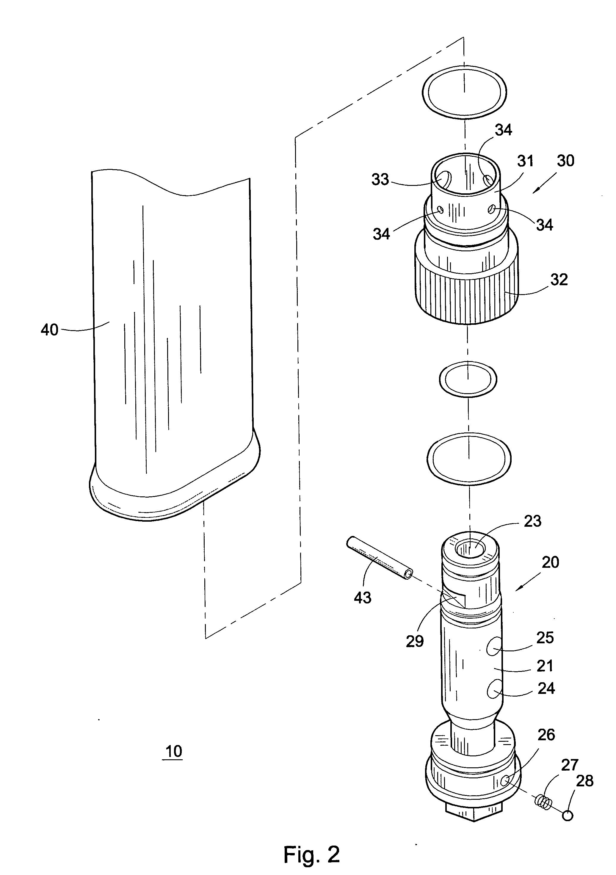
[0013] Please refer to FIGS. 1 to 5. The rotational speed adjustment mechanism 10 of the present invention includes an intake member 20, a speed adjustment valve 30 and a case 40.

[0014] The intake member 20 has an upright cylindrical body section 21 with a certain length. An intake 22 upward axially extends from the bottom end of the body section 21 by a certain depth. An exhaust port 23 downward axially extends from the top end of the body section 21 by a certain depth. The inner ends of the intake 22 and the exhaust port 23 are separated without communicating with each other. A lateral outlet 24 perpendicularly extends from one side of the inner end of the intake 22 through the wall of the body section. A lateral inlet 25 perpendicularly extends from one side of the inner end of the exhaust port 23 through the wall of the body section. The lateral outlet 24 and the lateral inlet 25 are parallel to each other, whereby the intake 22 and the exhaust port 23 are communicated with eac...


PUM


Abstract

A rotational speed adjustment mechanism of a pneumatic tool, including an intake member, a speed adjustment valve and a case enclosing the intake member and the speed adjustment valve. The intake member is formed with an intake and an exhaust port which are not communicated with each other. A lateral outlet and a lateral inlet are formed on the sidewall of the body section for communicating the intake with the exhaust port. The speed adjustment valve has a collar coaxially fitted on the body section and rotatable between a full speed position and a slowest speed position. A full speed through hole and at least one slow speed through hole are formed on the sidewall of the collar. When the collar is positioned in the full speed position, the full speed through hole is coaxially communicated with the lateral outlet, whereby the full diameter range of the lateral outlet provides a passage for the airflow. When the collar is positioned in the slowest speed position, the slow speed through hole is communicated with the lateral outlet, whereby simply the diameter range of the slow speed through hole provides a passage for the airflow.

Description

BACKGROUND OF THE INVENTION [0001] The present invention is related to a pneumatic tool, and more particularly to a rotational speed adjustment mechanism of a pneumatic tool. [0002] There are various conventional rotational speed adjustment mechanisms for controlling the rotational speed of the rotor of a pneumatic tool by means of controlling the flow of the air. In the conventional rotational speed adjustment mechanisms, a specially shaped valve stem is disposed in the air way between the air room and the internal intake passage of the handle for changing the rotational speed of the rotor. It is uneasy to manufacture and process the specially shaped valve stem. Therefore, it is hard to control the precision of the valve stem. [0003] Furthermore, the entire rotational speed adjustment mechanism is disposed in a middle position of the air way of the pneumatic tool. Therefore, when the high pressure air is filled up in the intake passage, the air pressure will lead to leakage of a pa...

Claims


Application Information

Patent Timeline
Patent Type & Authority Applications(United States)
IPC IPC(8): B25F5/00F16K11/076F16K11/085
CPCB25F5/00F16K11/085F16K11/076
Inventor CHUANG, CHIA-CHIUNG
Owner CHUANG CHIA CHIUNG
Why Eureka
Try Eureka