Non-slip rate-plated sta-bar bushing

a technology of sta-bar bushings and non-slip rate, which is applied in the direction of shock absorbers, machine supports, transportation and packaging, etc., can solve the problems of inability to accept the audible squawk in the vehicle, premature disassembly, and inability to disassemble, so as to eliminate the potential for an audible squawk, improve the durability of the bushing, and reduce the tendency of bushing walk-out

Inactive Publication Date: 2005-02-10
THE PULLMAN CO
View PDF9 Cites 11 Cited by
  • Summary
  • Abstract
  • Description
  • Claims
  • Application Information

AI Technical Summary

Benefits of technology

[0010] The present invention provides the art with an attachment between the stabilizer bar and the supporting structure of the vehicle which will improve the durability of the bushing, provide isolation for the stabilizer bar, allow for the proper positioning of the stabilizer bar relative to the frame and will eliminate and / or reduce the bushing walk-out tendency. The present invention provides for radial, axial, torsional and conical loading of the stabilizer bar due to jounce and rebound of the suspension. The present invention provides this relative movement between the stabilizer bar and the frame without slippage between the bushing and the stabilizer bar thus eliminating the potential for an audible squawk.
[0011] The present invention utilizes a mechanically bonded bushing assembly assembled over the stabilizer bar and then compressed into an outer sleeve / bracket assembly. The bracket assembly is provided with slotted holes to compensate for the stabilizer bar assembly and the vehicle body tolerance stack-ups. This preassembly of the bushing assemblies and the stabilizer bar also allows this assembly to be supplied directly to the assembly plants ready for vehicle assembly. This is opposed to the prior art which supplies the stabilizer bar and the bushings as separate components requiring sub-assembly at the vehicle assembly plant. The stabilizer bar attachment of the present invention provides both axial and lateral location proximate to the vehicle body and suspension attachments, the torsional resistance of the elastomeric member provides enhanced anti-roll capabilities, and due to the lack of slippage between the elastomeric member and the bore, a noise free pivot attachment with enhanced longevity and product life is provided. In addition, the design for the bushing assembly eliminates and / or reduces the tendency of the bushing assembly to walk-out of the sleeve / bracket assembly.
[0012] The bushing assembly of the present invention includes an elastomeric bushing within which a rate plate in the form of a rigid cylinder is molded. The rate plate is bonded to the bushing on both its interior and exterior surface. The rate plate adds considerable radial, torsional, conical and axial rate stiffness. In addition, the rate plate increases the confinement of the elastomeric bushing which is a key design consideration for bushing walk-out.

Problems solved by technology

The primary disadvantage of these designs is that the liner wears or the lubricant dissipates resulting in an unacceptable audible squawk in the vehicle.
Also, with these designs, environmental contamination can result in premature wear of the liner or premature dissipation of the lubricant thus leading to the audible squawk.
The designs that allow partial wind-up and then allow slippage of the stabilizer bar with respect to the bushing suffer from the same disadvantages as the designs that allow total rotation in that early wear and / or contamination of the interface between the bar and the bushing can lead to an audible squawk.
The designs that attempt to eliminate all slippage of the bushing have been successful for limited rotation of the stabilizer bar with respect to the bushing, but larger rotation of the stabilizer bar has caused deterioration of the bushing and / or slippage of the bushing.
While the incorporation of flats has resisted the larger amounts of rotation, the costs and complexities of these designs have limited their applicability.
While these designs have and continue to meet the needs of the vehicle designers, the bushing which is compressed and assembled into the outer sleeve / bracket assembly can be subject to walk-out of the bushing during vehicle operation.

Method used


Image

  • Non-slip rate-plated sta-bar bushing
  • Non-slip rate-plated sta-bar bushing
  • Non-slip rate-plated sta-bar bushing

Examples


Embodiment Construction

[0028] The following description of the preferred embodiment(s) is merely exemplary in nature and is in no way intended to limit the invention, its application, or uses.

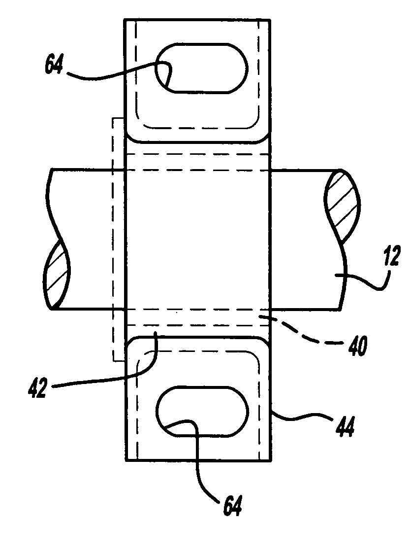
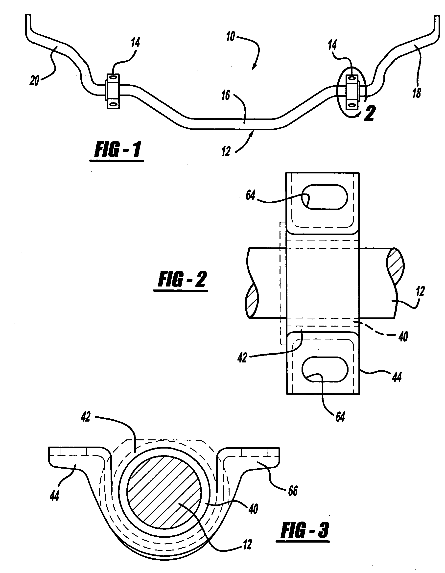
[0029] Referring now to the drawings in which like reference numerals designate like or corresponding parts throughout the several views, there is shown in FIG. 1 a stabilizer bar assembly which is identified generally by the reference numeral 10. Stabilizer bar assembly 10 comprises a stabilizer bar 12 and a pair of stabilizer bar bushing assemblies 14. Stabilizer bar 12 is a generally U-shaped bar having a center sectional 16 and a pair of end sections 18 and 20. Center section 16 is designed to be secured to the sprung mass of the vehicle by stabilizer bar bushing assemblies 14. End sections 18 and 20 are designed to be secured to the left and right suspension control arms or hubs (not shown) of the vehicle to which stabilizer bar assembly 10 is designed for. The various bends and unique configurations for stabil...


PUM


Abstract

A stabilizer bar assembly has a stabilizer bar and a pair of bushing assemblies. Each bushing assembly has an elastomeric bushing disposed around the stabilizer bar and an outer metal member disposed around the elastomeric bushing. The elastomeric bushing has a molded in rate plate to increase the stiffness of the elastomeric bushing. The outer metal member compresses the elastomeric bushing between the stabilizer bar and the outer metal member to a prespecified percent of compression. When the stabilizer bar rotates with respect to the outer metal member, the compression of the elastomeric bushing stops movement between the elastomeric bushing and the stabilizer bar and between the elastomeric bushing and the outer metal member. A fastening strap is attached to the outer metal member to attach the stabilizer bar assembly to a vehicle.

Description

CROSS-REFERENCE TO RELATED APPLICATIONS [0001] This application is a continuation-in-part of U.S. patent application Ser. No. 10 / 075,062 filed on Feb. 13, 2002, now U.S. Pat. No. 6,755,403 which is a continuation-in-part of U.S. patent application Ser. No. 09 / 408,406 filed Sep. 29, 1999, now abandoned.FIELD OF THE INVENTION [0002] The present invention relates to a stabilizer bar bushings. More particularly, the present invention relates to a stabilizer bar bushing which incorporates anti-slip features to eliminate slip between the bushing and the stabilizer bar and which incorporates a rate-plate to reduce and / or eliminate walk-out. BACKGROUND OF THE INVENTION [0003] Conventional motor vehicle suspension systems often include one or more stabilizer bars to control the degree of roll of the motor vehicle during cornering or other vehicle maneuvers. A typical stabilizer bar is generally U-shaped having a long intermediate portion disposed laterally with respect to the motor vehicle a...

Claims


Application Information

Patent Timeline
Patent Type & Authority Applications(United States)
IPC IPC(8): B60G21/055
CPCB60G21/0551
Inventor LEWIS, JAMESNOVY, RICHARDMISSIG, ROBERTFERGUSON, ROBERTFRANZEN, ANDREW
Owner THE PULLMAN CO
Why Eureka
Try Eureka