Fan system for vehicles and method for controlling fan in vehicles

Active Publication Date: 2005-02-10
TOYOTA JIDOSHA KK
View PDF6 Cites 13 Cited by
  • Summary
  • Abstract
  • Description
  • Claims
  • Application Information

AI Technical Summary

Benefits of technology

[0009] In view of the above problem, the invention has been made to provide a fan system for a vehicle and a method for controlling a fan provided in a vehicle, each enabling an easy check

Problems solved by technology

Consequently, even after the electric connection of the fan can no longer be checked visually after installed to the vehicle, the w

Method used


Image

  • Fan system for vehicles and method for controlling fan in vehicles
  • Fan system for vehicles and method for controlling fan in vehicles
  • Fan system for vehicles and method for controlling fan in vehicles

Examples


Embodiment Construction

[0026] Hereinafter, exemplary embodiments of the present invention will be described with reference to the accompanying drawings. In the following, like reference numerals will be used for like elements in each embodiment

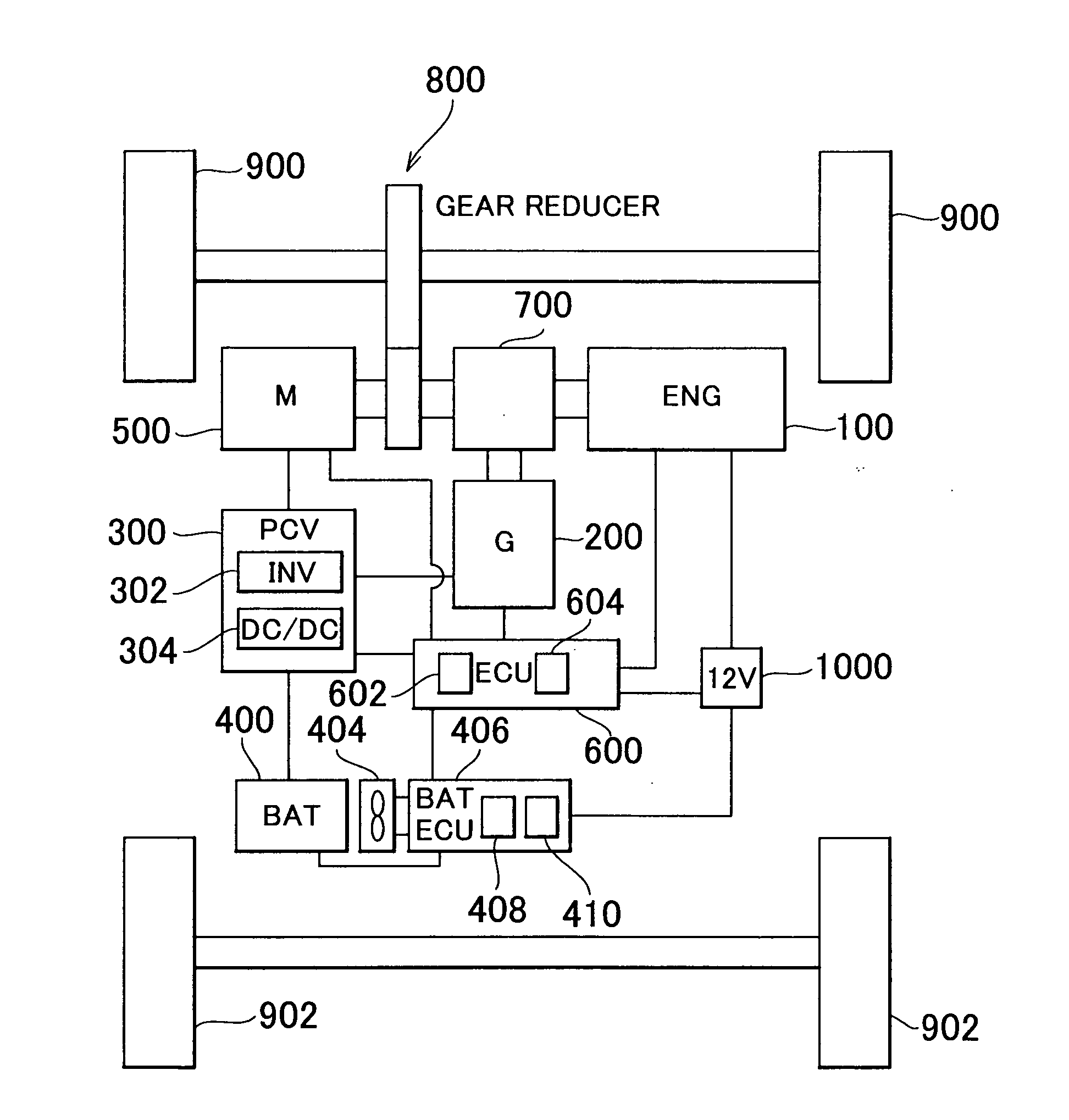
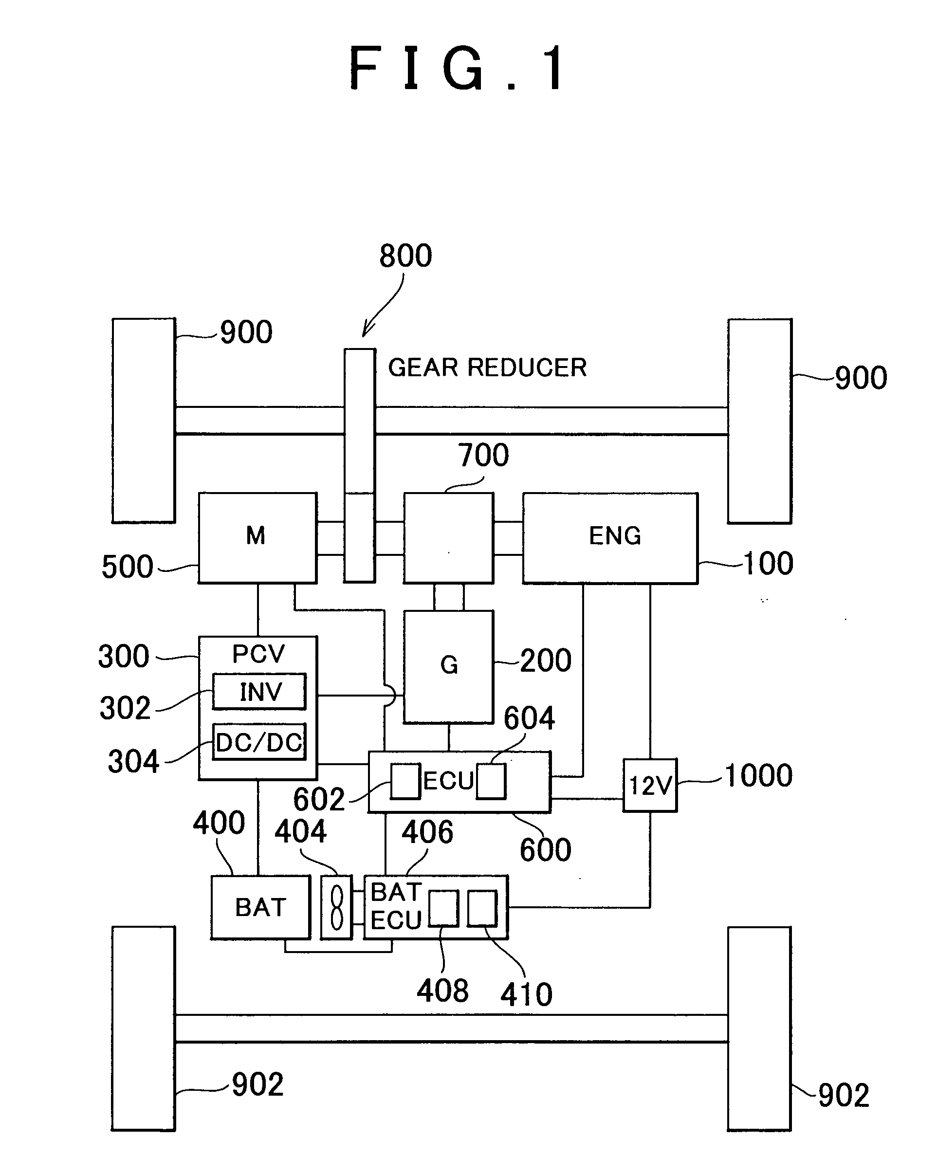
[0027]FIG. 1 schematically shows the configuration of a hybrid vehicle incorporating a fan system according to a first exemplary embodiment of the invention. Referring to FIG. 1, the hybrid vehicle includes an engine 100, a generator 200, a power control unit 300, a battery 400, a fan 404, a battery ECU (Electronic Control Unit) 406, a motor 500, a hybrid ECU 600, and an accessory battery 1000.

[0028] The driving force from the engine 100 is divided into two paths at a driving force distribution mechanism 700. One path leads to drive wheels 900 to drive them via a gear reducer 800 while another leads to the generator 200 to drive it for power generation. The driving force of the engine 100 is also used to drive a starter generator, not shown, to generate power, and...


PUM


Abstract

A fan system is provided which keeps a record of the electric connection between a battery ECU and an accessory battery and starts a fan if it is determined based on the record that the electric connection between the battery ECU and the accessory battery was just in an unconnected state.

Description

INCORPORATION BY REFERENCE [0001] The disclosure of Japanese Patent Application No. 2003-288822 filed on Aug. 7, 2003 including the specification, drawings and abstract is incorporated herein by reference in its entirety. BACKGROUND OF THE INVENTION [0002] 1. Field of the Invention [0003] The present invention relates to a fan system for vehicles and a method for controlling a fan in vehicles. [0004] 2. Description of the Related Art [0005] A wide variety of motor-driven vehicles (e.g., electric vehicles, hybrid motor vehicles, fuel-cell powered vehicles) is known and each of such vehicles usually includes a battery for powering the driving system of the vehicle and a fan system for cooling the battery since its capacity (performance) may otherwise decrease with increase in the temperature of the battery while charged and discharged repeatedly. [0006] Japanese Laid-opened Patent Application No. 2000-100481 discloses a battery assy for electric vehicles which enables the efficient us...

Claims


Application Information

Patent Timeline
IPC IPC(8): B60K1/04B60K6/445B60K11/06B60L1/00B60L3/00B60L11/18B60R16/03B60W10/26B60W10/30B60W20/00H01M10/60
CPCB60K1/04B60K6/445B60K2001/005B60L3/0046B60L3/0053B60L11/1874Y02T10/6239B60W10/26B60W10/30B60W20/00Y02T10/7005Y02T10/705Y02T90/34B60R16/03B60L58/12B60L58/18B60L58/26Y02T10/62Y02T10/70Y02T90/40
Inventor ARIDOME, KOJI
Owner TOYOTA JIDOSHA KK
Why Eureka
Try Eureka