Multiphase induction device

a multi-phase induction and induction device technology, applied in the direction of transformer/inductance details, basic electric elements, electrical equipment, etc., can solve the problems of high vibration noise and mechanical stress, magnetic field fringes, spread out and is less confined, and unwanted eddy currants and hot spots

Inactive Publication Date: 2005-02-10
ABB (SCHWEIZ) AG
View PDF4 Cites 54 Cited by
  • Summary
  • Abstract
  • Description
  • Claims
  • Application Information

AI Technical Summary

Benefits of technology

[0026] The conductivity of the two semiconducting layers is sufficient to substantially equalize the potential along each layer. The conductivity of the outer semiconducting layer is sufficiently high to enclose the electrical field within the cable, but sufficiently low not to give rise to significant losses due to currents induced in the layer.

Problems solved by technology

This is a source of vibrational noise and high mechanical stress.
Another problem associated with the air gap is that the magnetic field fringes, spreads out and is less confined.
Thus, field lines tend to enter and leave the core with a non-zero component transverse to the core laminations which can cause a concentration in unwanted eddy currants and hot spots in the core.
However, such inserts are complicated and difficult to manufacture and are therefore expensive.

Method used


Image

  • Multiphase induction device
  • Multiphase induction device
  • Multiphase induction device

Examples


Embodiment Construction

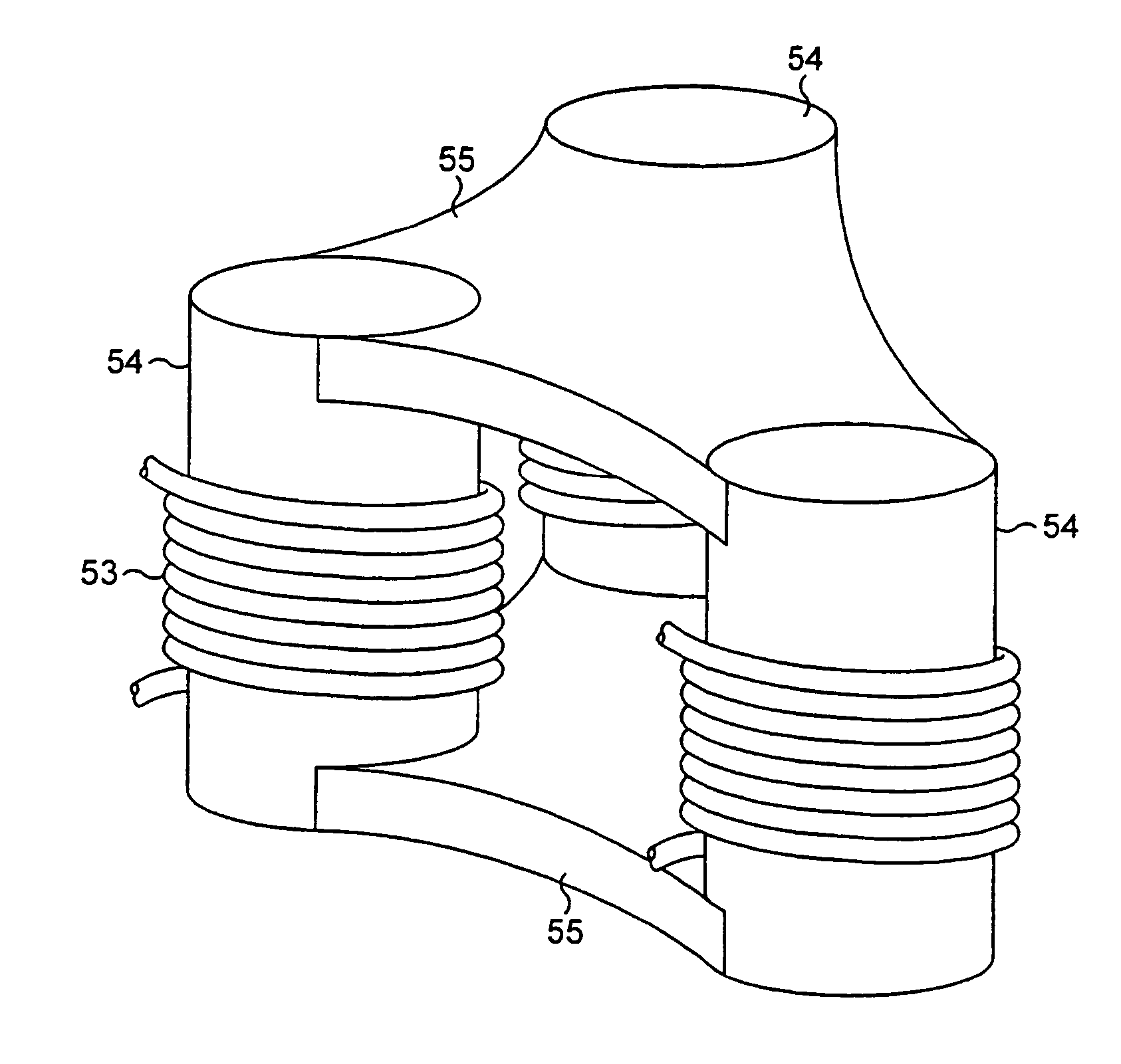
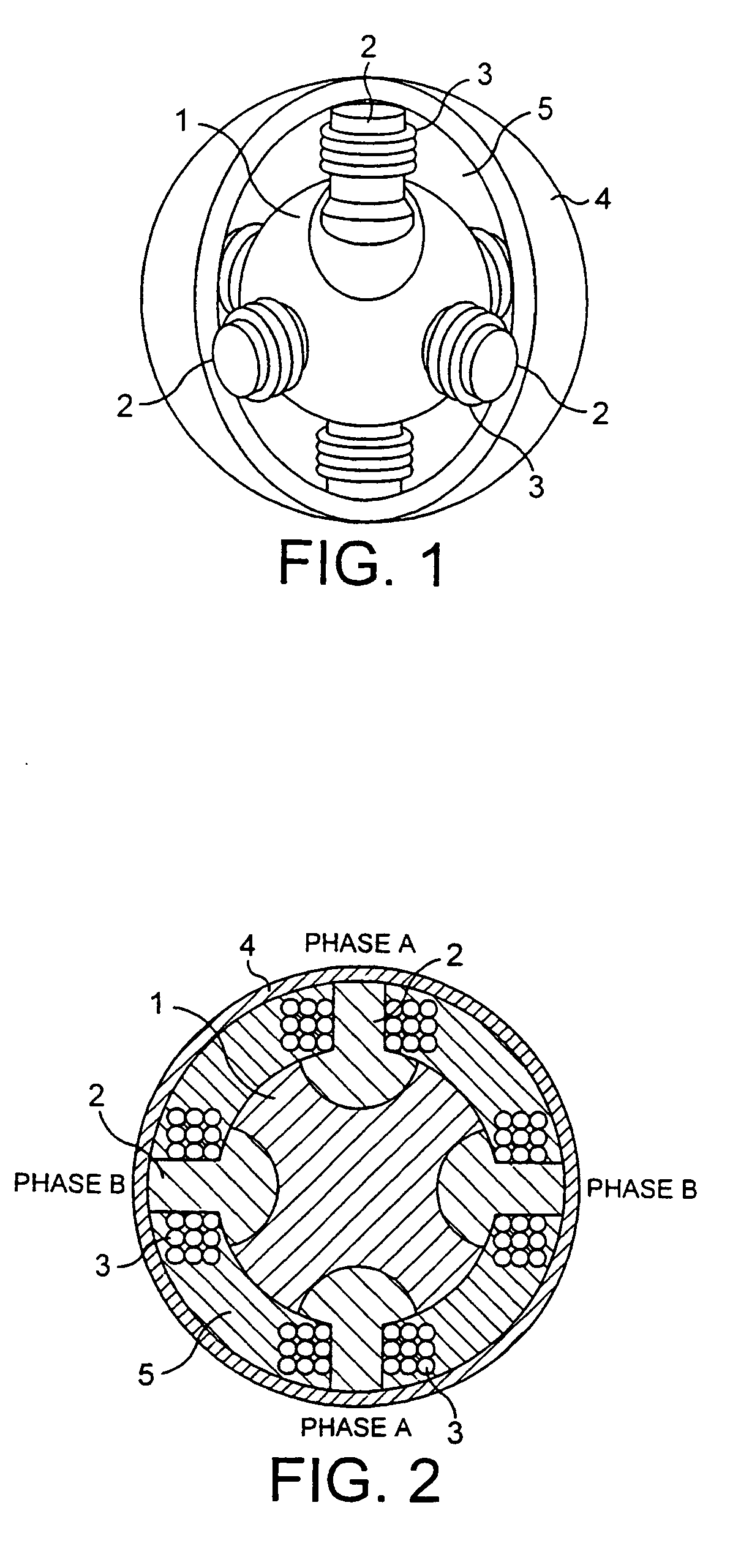
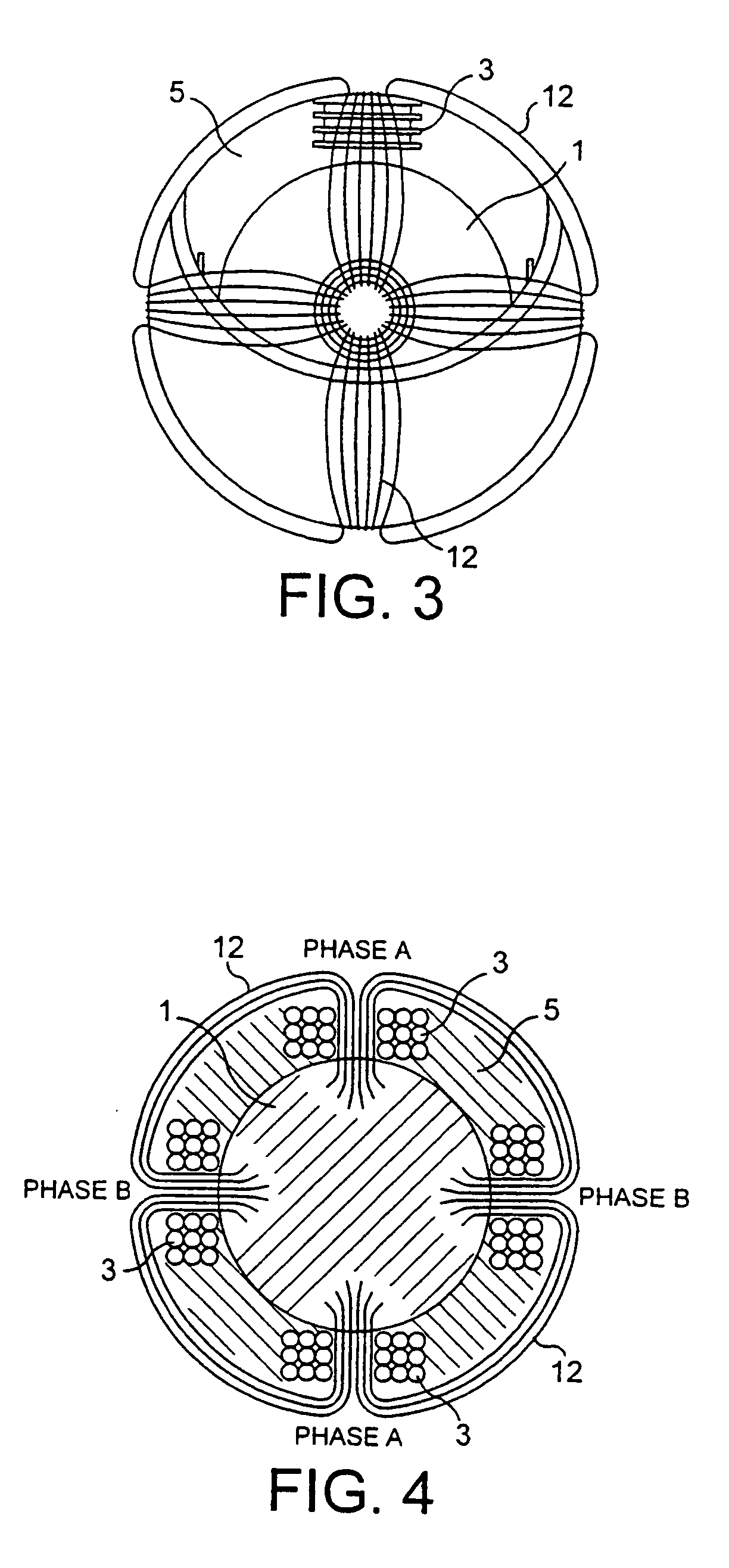
[0050]FIGS. 1 and 2 show a spherical three-phase reactor comprising a central substantially spherical body 1 of distributed air gap material. Six soft magnetic core limbs 2, lying along the major Cartesian co-ordinate axes, protrude from recesses in the body 1. More generally, the spherical reactor has 2n core limbs, spaced equiangularly, and in the embodiment shown n=3 and the limbs are spaced orthogonally. (In alternative embodiments there are 3n equiangularly spaced limbs.) However, n can be any natural number. Each core limb 2 carries a winding 3, with coaxial limbs carrying windings from the same phase, although the number of core limbs is not necessarily 2 per phase. An outer mantle 4 of ferrite, iron or other soft magnetic material closes the magnetic flux path and provides effective magnetic shielding. A fill material 5 with a relative magnetic permeability of approximately 1, such as concrete, may optionally fill the space between the body 1 and mantle 4.

[0051] Since the c...


PUM

PropertyMeasurementUnit
sizeaaaaaaaaaa
sizeaaaaaaaaaa
voltageaaaaaaaaaa

Abstract

An induction device, such as a transformer or reactor, which includes windings of different phases arranged around magnetic core limbs. The magnetic core limbs are connected by at least one body formed from magnetic particles in a matrix of a dielectric material. The device can also be substantially spherical or cylindrical. Regulating windings mounted on inner and outer magnetic core parts may be transferable between the inner and outer magnetic core parts.

Description

BACKGROUND TO THE INVENTION [0001] The present invention relates to an induction device, such as a reactor or transformer, having a plurality of phases. [0002] The invention is particularly applicable to a large reactor for use in a power system, for example in order to compensate for the Ferranti effect in long overhead lines or extended cable systems causing high voltages under open circuit or lightly loaded conditions. Reactors are sometimes required to provide stability to long line systems. They may also be used for voltage control and switched into and out of the system during lightly loaded conditions. [0003] Transformers are used in power systems to step up and step down voltages to useful levels. [0004] A typical known induction device comprises one or more coils wrapped around a laminated core to form windings, which may be coupled to the line or load and switched in and out of the circuit. The equivalent magnetic circuit of a static induction device comprises a source of ...

Claims


Application Information

Patent Timeline
Patent Type & Authority Applications(United States)
IPC IPC(8): H01F27/255H01F27/38H01F30/12
CPCH01F27/255H01F30/12H01F27/38
Inventor DAHLGREN, MIKAELFROMM, UDORUSSBERG, GUNNARSASSE, CHRISTIANERIKSSON, ANDERSJONSSON, TOMASSODERHOLM, SVANTE
Owner ABB (SCHWEIZ) AG
Why Eureka
Try Eureka