High performance ceramic fuel cell interconnect with integrated flowpaths and method for making same

a fuel cell and ceramic technology, applied in the direction of cell components, final product manufacturing, sustainable manufacturing/processing, etc., can solve the problems of excess fuel usage, poor stack efficiency, and increased demand for distributed generation systems, so as to achieve minimal resistive losses and sufficient conductivity

Inactive Publication Date: 2003-04-24
LG FUEL CELL SYST
View PDF7 Cites 43 Cited by
  • Summary
  • Abstract
  • Description
  • Claims
  • Application Information

AI Technical Summary

Benefits of technology

0021] The present invention provides an interconnect for a solid oxide fuel cell consisting of multiple ceramic layers. These multiple layers perform two distinct functions: separation and containment of the reactant gases by way of a multi-layer ceramic article; and collection and conduction of electrical current produced by the adjacent anode-electrolyte-cathode tri-layer by way of conductive vias. The via material must have sufficient conductivity so that the electric current can flow through the interconnect from one cell to an adjacent cell with minimal resistive losses. Air and fuel gas separation is accomplished using one or more dense ceramic layers having dense conductive filled vias integrated therein. Air and fuel flow passages are formed using multiple ceramic layers on each side of the separator layer(s). Overlapping holes (or other structures such as slots) in adjacent layers produce the required reactant flow channels. The size and spacing of the holes (or slots) and the thickness of the layers determines the gas flow distribution and the pressure drop.

Problems solved by technology

Moreover, as demand continues to increase, many anticipate that the demand for distributed generation systems will also increase.
However, the construction and operating costs of solid oxide fuel cells must compare favorably with these alternative power sources.
This excess fuel usage has a negative impact on the overall cell and stack efficiency.
Notwithstanding the issues associated with the negative impact of improper reactant flow on performance, SOFC interconnect functionality and interconnect cost actually constitute the greatest barriers to producing market competitive SOFC systems at present.
However, both types of interconnects are expensive and compromise aspects of the interconnect function.
Moreover, lanthanum chromite and high-temperature alloys (for example, high chrome alloys) used in a conventional monolithic interconnect design are currently cost-prohibitive, although use of lanthanum chromite interconnect could theoretically allow for a marginally competitive product, assuming a regular, high production volume was needed and net-shape ceramic processing was used.
The gas separation requirement presents another problem in terms of materials selection.
Although ceramic processing has developed the capability to produce interconnects of sufficiently high density, many ceramics, including lanthanum chromite, have an unacceptably high ionic conductivity (thereby resulting in poor system performance).
Many electrically conductive ceramic materials also exhibit undesired dimension changes when subjected to reducing gas atmospheres due to the loss of oxygen ions within the material.
Alternate compositions of ceramic materials possessing low ionic conductivity generally have less than acceptable electronic conductivity or have a coefficient of thermal expansion (CTE) that is not well matched to that of the cell.
In contrast, metallic alloy interconnects have been developed that readily satisfy the gas separation function, but they generally do not exhibit adequate resistance to corrosion (and other deleterious reactions).
In particular, oxide scale growth / formation and unacceptably high electrical resistance are probably the most challenging hurdles presented by known metal interconnects.
Porous or laminar scales have the effect of increasing the current path length while reducing the effective current carrying cross sectional area.
The application of coatings to alloy interconnects also increases the fabrication cost.
Too large of a mismatch of CTE results in certain regions of the cell becoming adversely displaced.
This physical displacement prevents effective confinement of the reactant gases within their intended flow paths, thereby adversely effecting performance of the entire SOFC stack.
While changes between room and operating temperatures (generally in the range of 700 to 1000.degree. C.) produce the largest thermal displacements, smaller temperature gradients across the stack (which vary with stack operating conditions) can also create detrimental displacements.
Dissimilar thermal expansion characteristics may also cause disruption of the electrical current path between cells and interconnects in a stack because of the relative movement of the contact points.
Essentially, this loss of contact creates additional, unwanted resistance which substantially degrades stack performance and efficiency.
As a result, metallic alloy interconnects are particularly susceptible to contact resistance problems because the relative motion caused by expansion can dislodge a protective oxide scale and expose underlying unprotected metal.
In turn, oxidation of any unprotected surface increases the overall scale thickness, and as mentioned above, the scale conductivity is comparatively poor so that such scale growth contributes directly to performance degradation.
In such cases, relative motion can actually crack or damage the electrodes or the electrolyte layer itself.
Generally, the CTE of chromite ceramic interconnects is more closely matched to the cell; however, other concerns make these interconnects less attractive.
While Hartvigsen's design provides the resulting cell / stack with the gas separation qualities (by way of the separator plate) and excellent current collection and conduction (by way of the filled vias), Hartvigsen fails to discuss any means for optimizing the reactant flowfields, nor does it imply these items could be integrated into the interconnect itself.
However, the staging plates of this pending application must be provided separately from the interconnect itself, and the application fails to consider any sort of integrated structure.

Method used


Image

  • High performance ceramic fuel cell interconnect with integrated flowpaths and method for making same
  • High performance ceramic fuel cell interconnect with integrated flowpaths and method for making same
  • High performance ceramic fuel cell interconnect with integrated flowpaths and method for making same

Examples


example ii

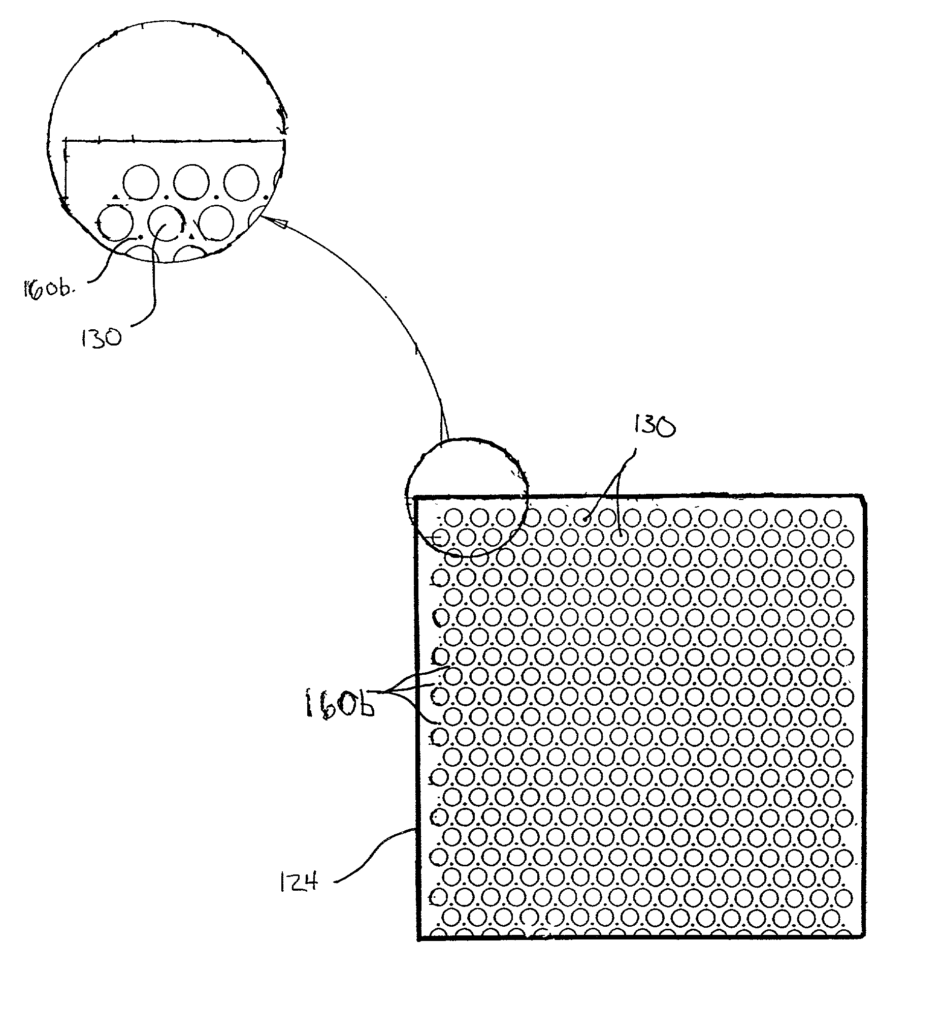
[0078] A second example focuses upon bore-coated vias, in contrast to the solid vias of Example I above. As mentioned above, the conductivity for the via conductor(s) must be relatively high in order to achieve the desired level of resistance for the interconnect. For the design shown in Example I, the target resistance may be achieved using vias having a diameter of 0.5 mm when the via material has a conductivity of about 600 S / cm or higher. However, for the air-side vias, it may be difficult to develop materials having sufficient conductivity, while at the same time having an acceptable CTE match.

[0079] As mentioned above, one possible approach to attacking this issue is to simply make the vias larger. However, the diameter of solid vias is generally limited to about the thickness of each individual layer due to the difficulties encountered in constructing the ceramic sheets. Bore-coated vias provide alternative conducting pathways within the gas flow structures that allows the us...

example iii

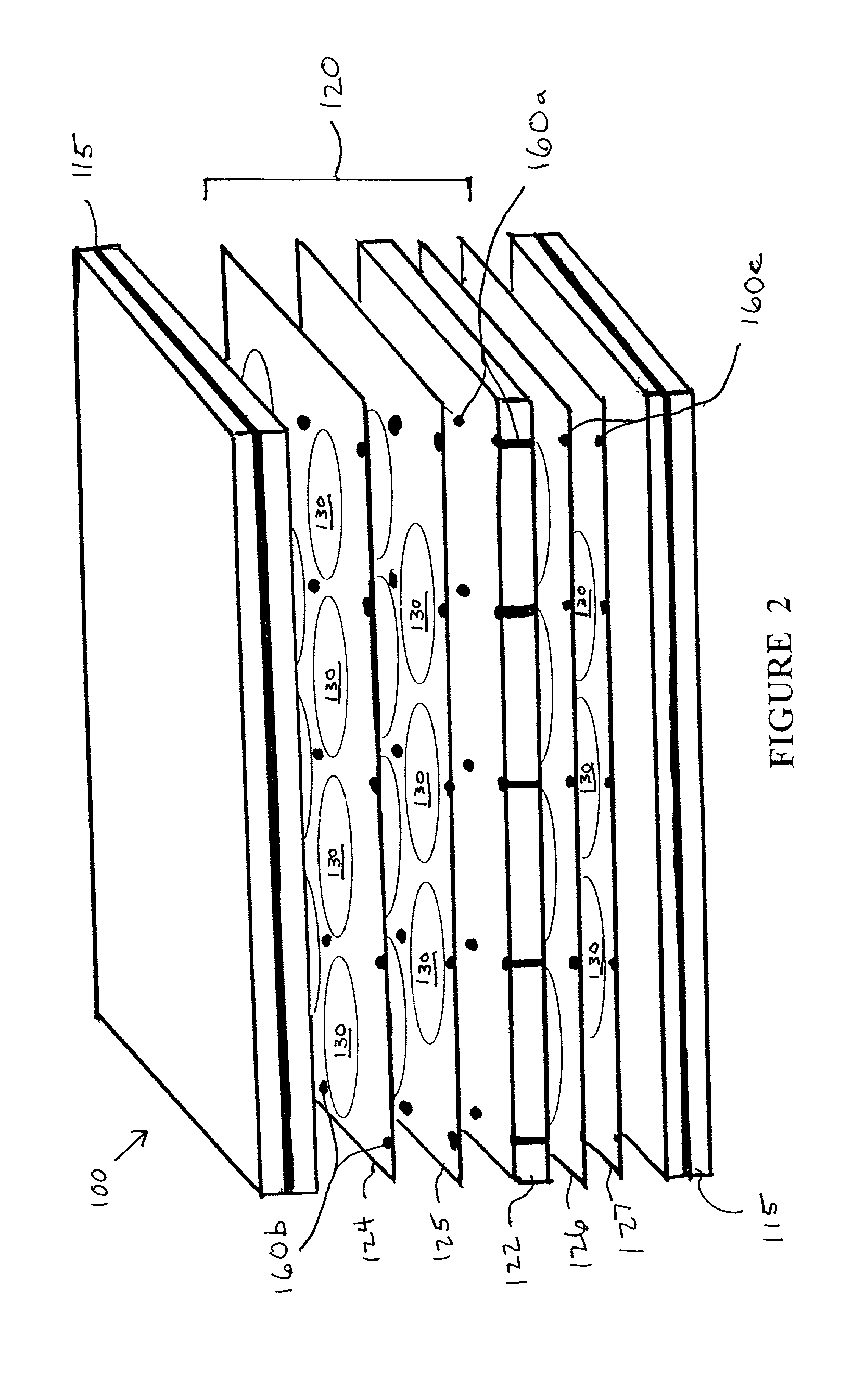
[0088] A final example focuses on a co-flow design having solid-filled vias and individual channel shaped apertures within the ceramic sheets. The design includes initial distribution plenums, thereby facilitating co-flow or counter-flow arrangements for fuel and airflow. A slot-like arrangement of apertures are individually connected to the plenum via a series of restrictive orifices, and further downstream, cross-flow between the individual slots is optimally minimized or eliminated altogether. Such an arrangement should be a co-flow configuration in order to allow for better distribution of reactant gases and overall performance control for the stack. This setup is also in contrast to the overlapping holes and cross-flow arrangement in Example I. This particular design may also be easily converted into a counter-flow configuration simply by providing the reactant gas sources at opposite ends of the stack.

[0089] Use of elongated slots should facilitate the creation of a via arrang...


PUM

PropertyMeasurementUnit
operating temperaturesaaaaaaaaaa
thicknessaaaaaaaaaa
thicknessaaaaaaaaaa

Abstract

A method, apparatus and assembly related to solid oxide fuel cell interconnects is disclosed. In its broadest embodiment, the invention contemplates a multi-layered ceramic interconnect having integrated flow fields and electrical connections. The method of making this interconnect includes judicious selection of materials, formation of appropriate apertures for the flow fields and electrical connectors, and the joining of the layers through a firing and/or sealing process.

Description

FIELD AND BACKGROUND OF INVENTION[0001] The present invention is generally drawn to a fuel cell interconnect and more particularly to a multi-layered ceramic interconnect possessing superior design and performance characteristics, as well as a method for making the same.[0002] Demand for electrical generating equipment has increased substantially in recent years. As a result, numerous technologies have been developed to provide electricity, including traditional grid-based systems and more localized, distributed generation systems. Moreover, as demand continues to increase, many anticipate that the demand for distributed generation systems will also increase.[0003] In response to this distributed generation need, particular attention has been paid to fuel cell systems. Fuel cells are electrochemical devices that convert the energy of a chemical reaction directly into electrical energy. The basic physical structure of a single fuel cell includes electrodes (an anode and a cathode) wi...

Claims


Application Information

Patent Timeline
Patent Type & Authority Applications(United States)
IPC IPC(8): H01M8/02H01M8/12H01M8/24H01M50/529
CPCH01M8/0215H01M8/0228H01M8/0256H01M8/0258Y10T29/4911H01M8/0297H01M8/12H01M8/24Y02E60/50H01M8/0271H01M8/0276Y02P70/50H01M8/2432H01M8/026
Inventor CABLE, THOMAS L.KNEIDEL, KURT E.BARRINGER, ERIC A.YUAN, THOMAS C.
Owner LG FUEL CELL SYST
Why Eureka
Try Eureka