Electronic imaging apparatus

a technology of electronic imaging and zoom lens, which is applied in the direction of cameras, television systems, instruments, etc., can solve the problems of unfavorable bottleneck in thinning the thickness of the depth direction of the camera, and achieve the effects of low aberration, low cost and low cos

Inactive Publication Date: 2005-02-10
OLYMPUS CORP
View PDF7 Cites 13 Cited by
  • Summary
  • Abstract
  • Description
  • Claims
  • Application Information

AI Technical Summary

Benefits of technology

According to the present invention, it is composed such that by inserting a reflecting optical element such as a reflecting prism or the like at an object side, an optical path (optical axis) of an optical system, particularly a zoom lens system is bent, and furthermore conditions mentioned above are satisfied. By such composition, a camera which has no start-up time (a time for pushing out a lens holding body) which is seen in a camera using a collapsible type camera body and is desirable for waterproof and dust-protection, and has a very thin in depth can be realized, while keeping a high optical specification performance, such as a zoom ratio, an angle of view, F value and little aberration. Moreover, unlike other zoom optical systems such as a zoom lens system suitable for a collapsible-body type camera, according to the present invention, miniaturization and thinning of the camera using a miniaturized imaging element can be carried out advantageously when miniaturization of an imaging element progresses further from now on.

Problems solved by technology

Generally, the most unfavorable bottleneck in thinning a thickness of the depth direction of a camera is an optical system, particularly a thickness from a surface at utmost object side to an imaging surface.

Method used


Image

  • Electronic imaging apparatus
  • Electronic imaging apparatus
  • Electronic imaging apparatus

Examples


first embodiment

The First Embodiment

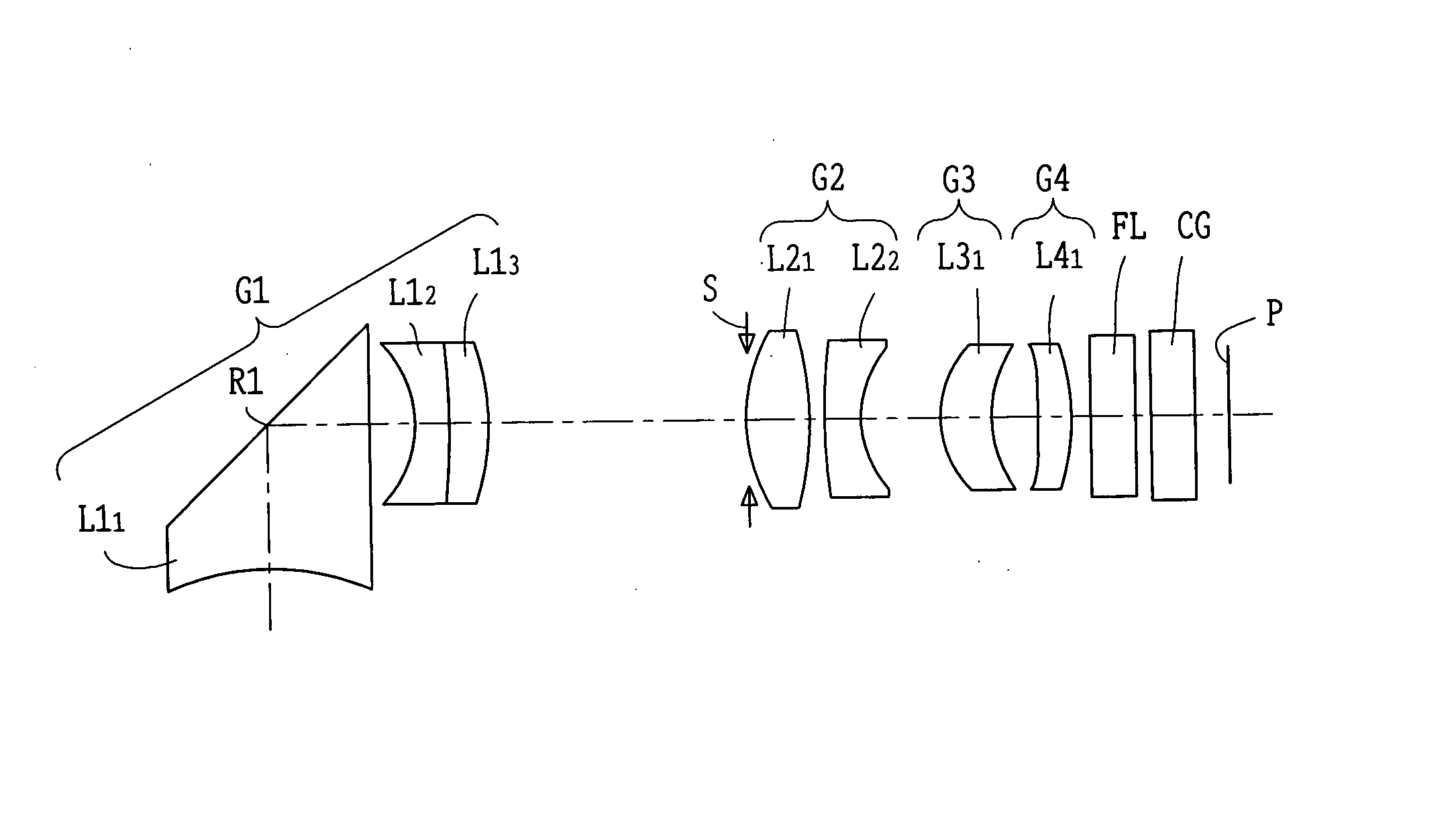
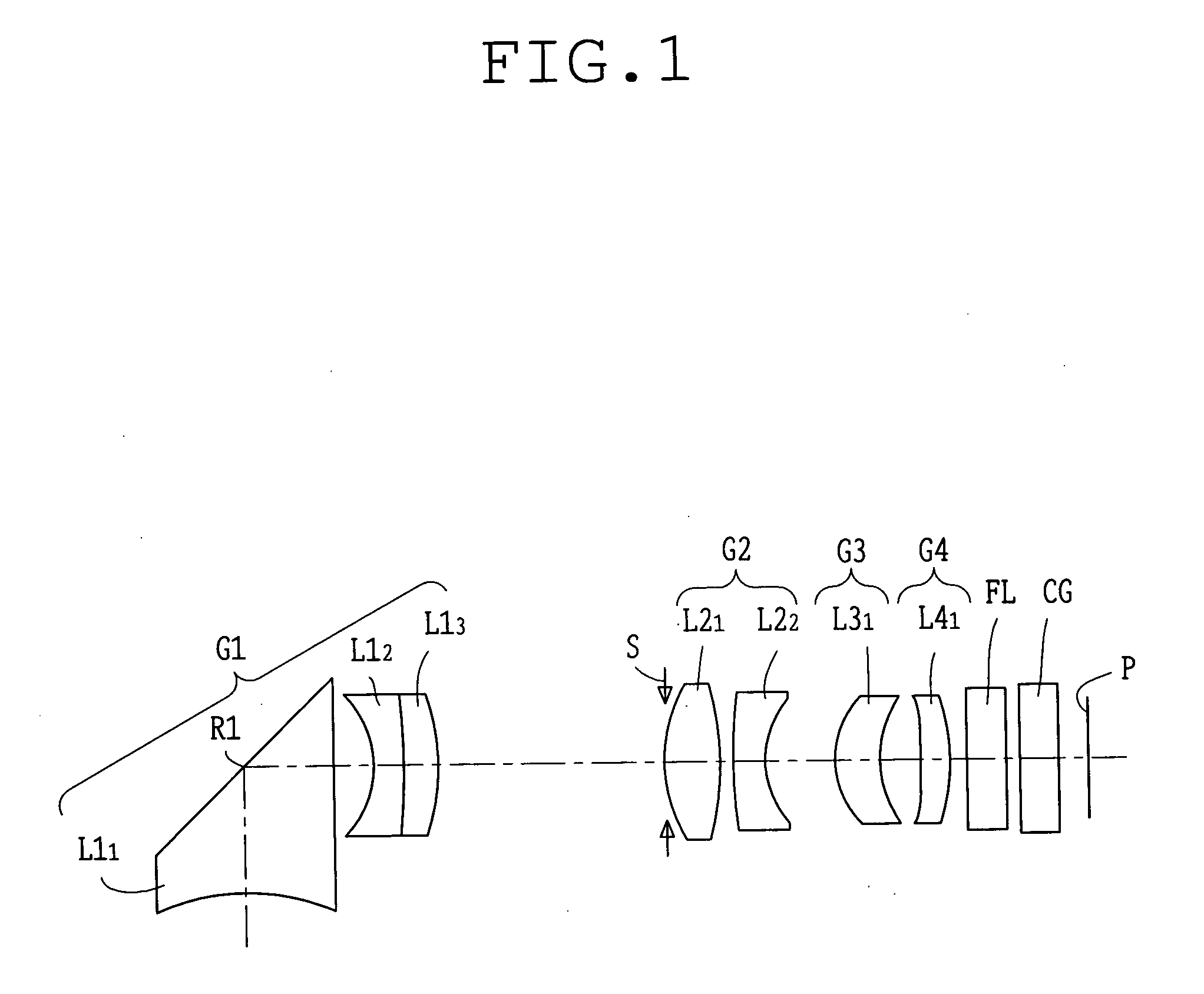
FIG. 1 is a sectional view showing an optical arrangement developed along the optical axis when focusing of an object point at the wide angle end is carried out at the time of bending the optical path in the first embodiment of the zoom lens used in the electronic imaging apparatus according to the present invention. FIGS. 2A, 2B and 2C are sectional views showing an optical arrangement developed along the optical axis when focusing of an object point is carried out at the wide angle end, the middle position and the telephoto end respectively, of the zoom lens in the first embodiment according to the present invention. FIGS. 3A to 3D, 3E to 3H, and 3I to 3L are aberration diagrams showing spherical aberration, astigmatism, distortion and chromatic aberration of magnification when focusing of the object point is carried out at the wide angle end, the middle position and the telephoto end respectively, of the zoom lens in the first embodiment.

The electronic imagi...

second embodiment

The Second Embodiment

FIG. 4 is a sectional view showing an optical arrangement developed along the optical axis when focusing of an object point at the wide angle end is carried out at the time of bending the optical path in the second embodiment of the zoom lens used in the electronic imaging apparatus according to the present invention. FIGS. 5A, 5B and 5C are sectional views showing an optical arrangement developed along the optical axis when focusing of an object point is carried out at the wide angle end, the middle position and the telephoto end respectively, of the zoom lens in the second embodiment according to the present invention. FIGS. 6A to 6D, 6E to 6H, and 6I to 6L are aberration diagrams showing spherical aberration, astigmatism, distortion and chromatic aberration of magnification when focusing of an object point is carried out at the wide angle end, the middle position and the telephoto end respectively, of the zoom lens in the second embodiment.

The electronic im...


PUM


Abstract

An electronic imaging apparatus of the present invention comprises a photographing optical system, in order from an object side, a first lens group having negative refracting power, which has a reflecting component having a reflecting surface for bending an optical path of an incident light from the object side and at least two positive lens groups arranged at an image side of the first lens group, wherein the photographing optical system is a zoom optical system and the following condition is satisfied: −1.75<f1 / fw<−0.8 where f1 is a focal length of the first lens group, and fw is a focal length at the wide angle end at the photographing optical system.

Description

BACKGROUND OF THE INVENTION 1. Field of the Invention This invention relates to a zoom lens and an electronic imaging apparatus using the same, particularly an electronic imaging apparatus including a video camera and a digital camera for which thinning of depth direction has been realized by devising an portion of the optical system of the zoom lens etc., and a zoom lens used in the same. 2. Description of the Related Art In recent years, a digital camera (electronic camera) has attracted an attention as a next generation camera which replaces 35 mm-silver-haloid film (135 format) camera. Furthermore, it has become many categories in wide range from a highly efficient type for business-use to a popular portable type. Generally, the most unfavorable bottleneck in thinning a thickness of the depth direction of a camera is an optical system, particularly a thickness from a surface at utmost object side to an imaging surface. Recently, a mainstream of technology for thinning a c...

Claims


Application Information

Patent Timeline
Patent Type & Authority Applications(United States)
IPC IPC(8): G02B13/00G02B13/18G02B17/08G02B15/167G03B17/17H04N5/225H04N101/00
CPCG02B5/04H04N5/2254G02B15/177G02B15/144507
Inventor MOROOKA, MASARU
Owner OLYMPUS CORP
Why Eureka
Try Eureka