This helps you quickly interpret patents by identifying the three key elements:
Problems solved by technology
Method used
Benefits of technology
Benefits of technology
It is therefore an object of the present invention to provide a transmitting type liquid crystal display which prevents downward gray scale inversion of a liquid crystal panel, considerably improves visual angle properties, prevents reflection of stray light, and improves front contrast and image clarity.
Although many techniques have been proposed to collect backlight, there were so far no techniques which took account of the gray scale property of the liquid crystal cell, and which, in order to reduce light at an angle larger than the angle at which gray scale inversion occurs, ensure that the light emitted from the backlight at an angle larger than the angle at which gray scale inversion occurs, is dispersed in another direction. It was also found that by controlling the haze value of the optical diffusion film on the visual recognition side of the liquid crystal cell and laminating a low refractive index layer on this optical diffusion film, reflection of stray light could be prevented and visual field angle improved without sacrificing the blurring of the image.
In the liquid crystal display of the present invention, the liquid crystal display comprises a backlight, an anisotropic scattering film having different scattering properties depending on incident angles, a liquid crystal cell containing liquid crystals sandwiched between two facing substrates, polarizing plates respectively disposed on the backlight side and visual recognition side of the liquid crystal cell, and at least one optical diffusion film on the visual recognition side of the liquid crystal cell, and the gray scale inversion angle of the liquid crystal display can be improved by disposing, between the backlight and liquid crystal cell, an anisotropic scattering film for which the difference H(θ)−H(0) between the haze H(θ) for light incident at a gray scale inversion angle θ of the liquid crystal cell, and the haze H(0) for light incident from the normal direction of this anisotropic scattering film, is from 5% to 100%. Further, the gray scale inversion angle of the liquid crystal display can be largely improved by providing an optical diffusion film for which the scattered light intensity at 30° relative to the light intensity at an emission angle of 0° in the scattered light angle distribution on the visual recognition side of the liquid crystal cells, is from 0.01% to 0.2%, and the haze H(0) is 40% or more. As a result, the visual angle properties can be considerably improved, reflection of stray light can be prevented, and a high performance transmission type liquid crystal display having enhanced front contrast and image clarity can be provided.
Problems solved by technology
However, if the incident light on the wide angle side is severely decreased taking the gray scale inversion angle as a borderline as described above, the luminosity variation largely increases when the visual angle is inclined, and the display quality deteriorates.
On the other hand, if the directivity of the incident light to the liquid crystal cell is narrowed and light is scattered too much by the optical diffusion film on the visual recognition side, back scattering becomes large, front luminosity decreases and image clarity deteriorates.
Method used
Image
Click on the blue label to locate the original text in one second.
Reading with bidirectional positioning of images and text.
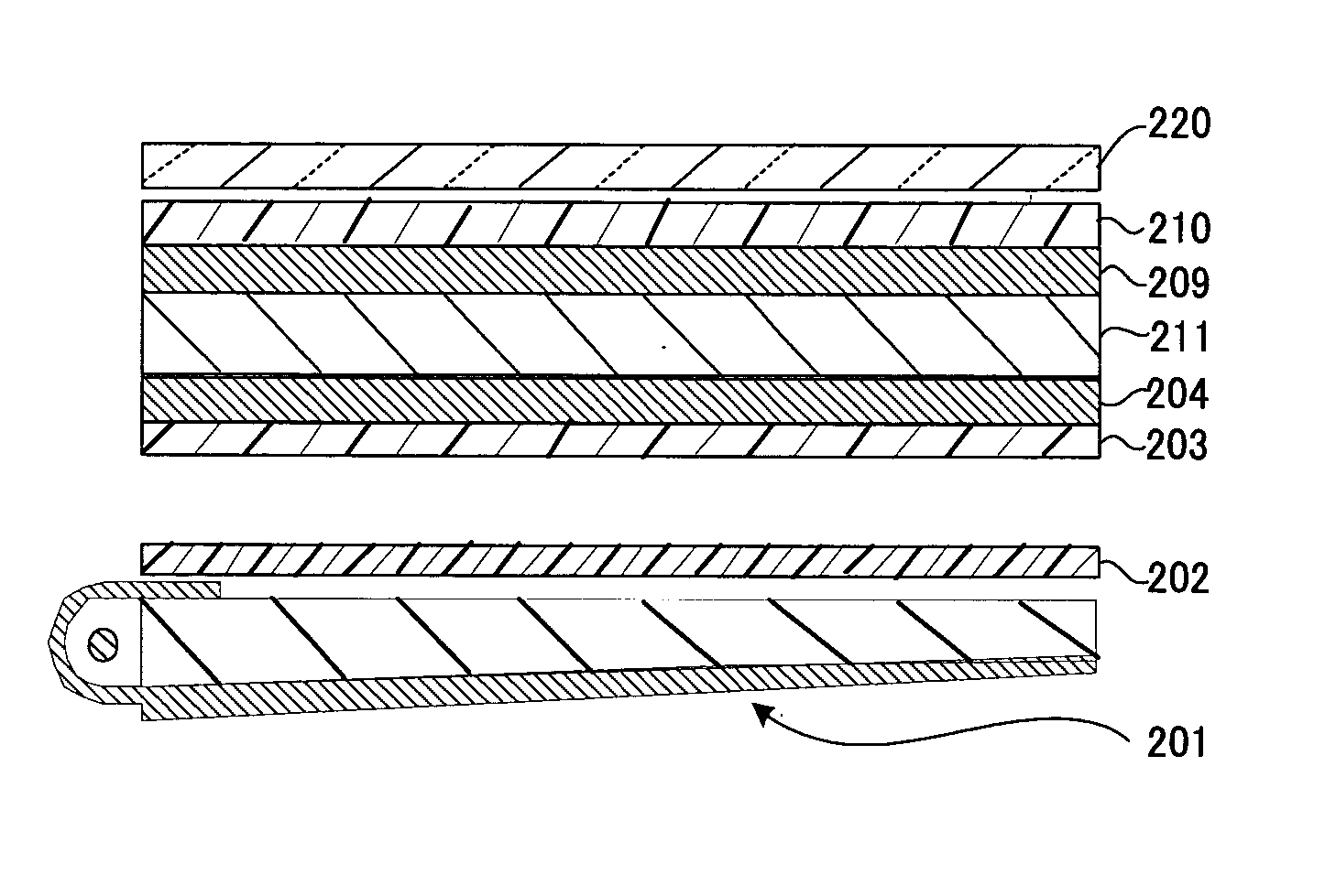
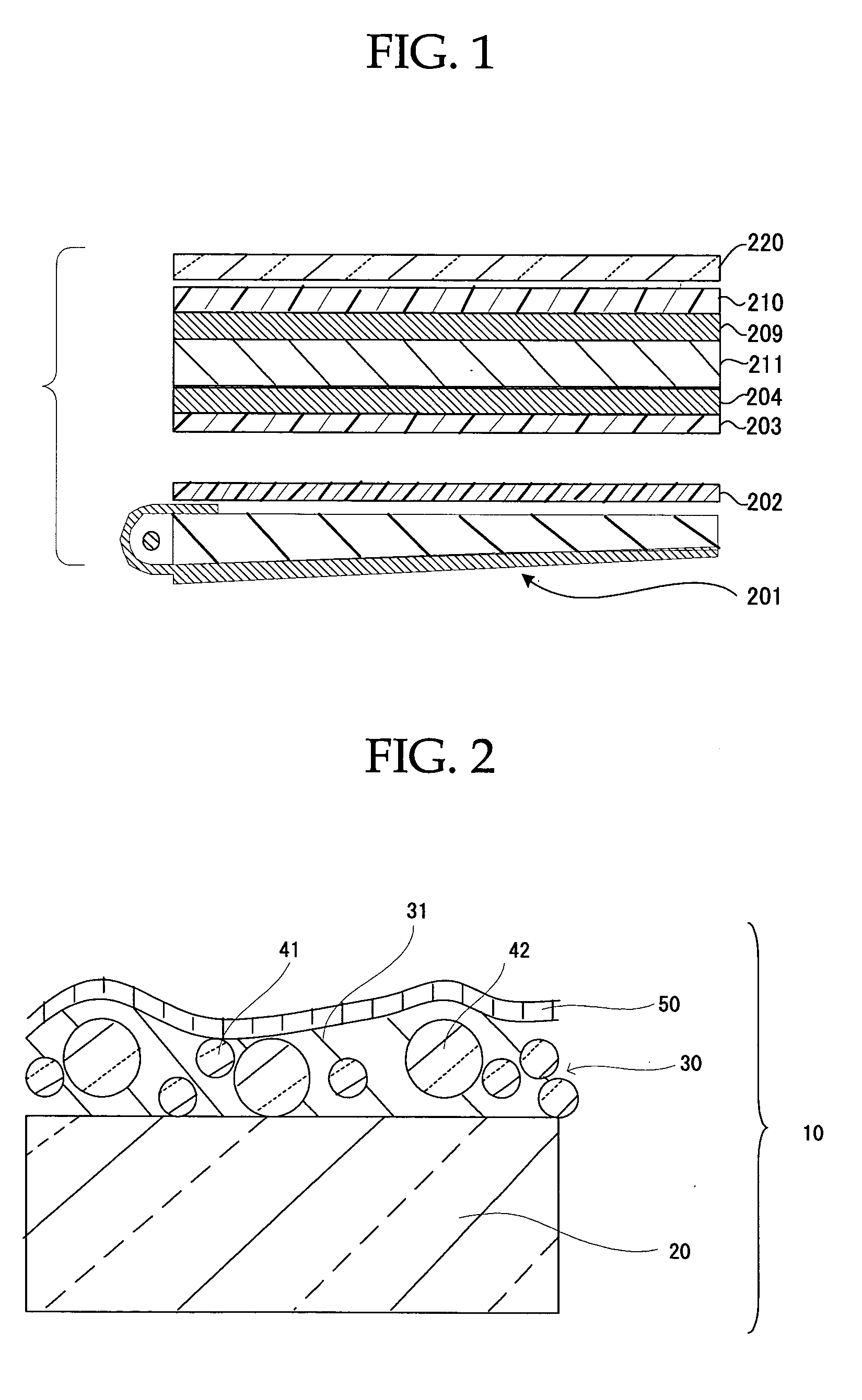
The pair of polarizing plates provided in the liquid crystal display (TH-14TA3, Matsushita Electric Industrial Co., Ltd.) using a TN type liquid crystal cell were peeled off, and instead, the visual recognition side polarizing plate (PB-02) on the observer side, and a backlight side polarizing plate on the backlight side, were respectively stuck via an adhesive so that the optical compensation film was on the liquid crystal cell side. The transmission axis of the polarizing plate on the observer side and the transmission axis of the polarizing plate on the backlight side were disposed in the 0 mode. “MFZ-2555” (LUMISTY, Sumitomo Chemical Co., Ltd.) as an anisotropic scattering film was also disposed between the backlight and liquid crystal cell so that its scattering anisotropy corresponded to the up / down direction of the liquid crystal display.
The construction of the liquid crystal display of Example 1 is shown in FIG. 8. In FIG. 8, 201 is ...
The liquid crystal display of Example 2 was manufactured exactly as in Example 1, except that in Example 1, the visual recognition side polarizing plate (PB-02) was replaced by the visual recognition side polarizing plate (PA-02). The construction of the liquid crystal display of Example 2 is shown in FIG. 9. In FIG. 9, 201 is a back light unit, 202 is an anisotropic scattering film, 203 is a polarizing film, 204 is an optically anisotropic layer, 209 is an optically anisotropic layer, 210 is a polarizing film, 211 is a liquid crystal cell, and A-02 is an optical diffusion film, respectively.
The liquid crystal display of Example 3 was manufactured exactly as in Example 1, except that in Example 1, the visual recognition side polarizing plate (PB-02) was replaced by the visual recognition side polarizing plate (PA-01).
The construction of the liquid crystal display of Example 3 is shown in FIG. 10. In FIG. 10, 201 is a back light unit, 202 is an anisotropic scattering film, 203 is a polarizing film, 204 is an optically anisotropic layer, 209 is an optically anisotropic layer, 210 is a polarizing film, 211 is a liquid crystal cell, and A-01 is an optical diffusion film, respectively.
BACKGROUND OF THE INVENTION 1. Field of the Invention The present invention relates to a highly efficient transmitting type liquid crystal display which can prevent downward gray scale inversion of a liquid crystal panel, considerably improve a visual angle property, and prevent reflection of stray light. 2. Description of the Related Art In general, a liquid crystal display comprises a polarizing plate and a liquid crystalcell. One of the defects in the display quality of this liquid crystal display, is a narrow visual angle and reflection of stray light, and it was desired to develop a liquid crystal display without these faults. As to the visual angle dependence of TN mode TFT liquid crystal displays which are the most common today, it is known that by inserting an optical compensation film between the polarizing plate and the liquid crystal cell, the visual angle can be expanded (“Liquid Crystal Display Introduction Lecture No. 11: Technique of Expanding Visual Angle of a ...
Claims
Application Information
Patent Timeline
Application Date:The date an application was filed.
Publication Date:The date a patent or application was officially published.
First Publication Date:The earliest publication date of a patent with the same application number.
Issue Date:Publication date of the patent grant document.
PCT Entry Date:The Entry date of PCT National Phase.
Estimated Expiry Date:The statutory expiry date of a patent right according to the Patent Law, and it is the longest term of protection that the patent right can achieve without the termination of the patent right due to other reasons(Term extension factor has been taken into account ).
Invalid Date:Actual expiry date is based on effective date or publication date of legal transaction data of invalid patent.

