
Projection type video display

a projection lens and video display technology, applied in the direction of printers, instruments, cameras focusing arrangements, etc., can solve the problems of large clearance between the projection lens and the aperture of the front cover, which not only loses design, but also allows dust to easily enter the frame of the projector, so as to achieve the effect of wide lens shift width

Active Publication Date: 2005-02-10
SANYO ELECTRIC CO LTD
View PDF5 Cites 23 Cited by
  • Summary
  • Abstract
  • Description
  • Claims
  • Application Information

AI Technical Summary

Benefits of technology

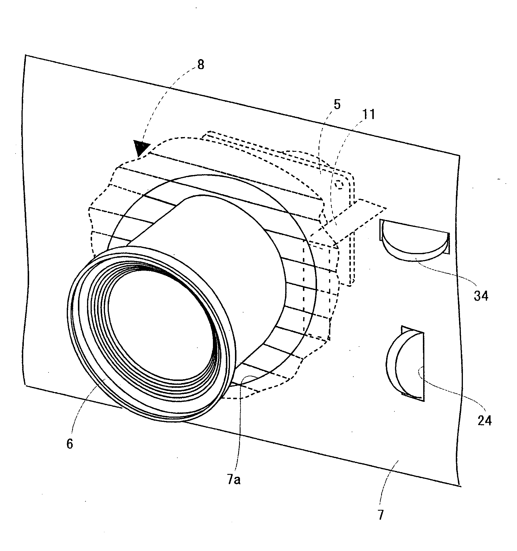
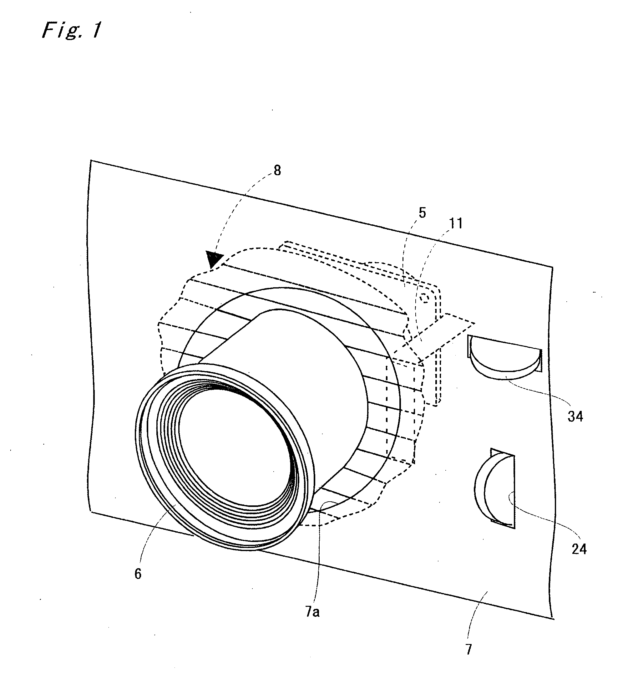
[0003] In a lens shift mechanism, a relatively large lens shift width can be ensured in a vertical direction (lengthwise) or a horizontal direction (crosswise). For this purpose, a large clearance must be ensured between a projection lens and an aperture of a front cover in a liquid crystal projector in correspondence with the lens shift width. However, the large clearance between the projection lens and the aperture of the front cover not only loses design but also allows dust to easily enter a frame of the projector.
[0004] In view of the foregoing circumstances, an object of the present invention is to provide a projection type video display capable of further preventing dust from entering its frame even when a large clearance is ensured between the projection lens and an aperture of a front cover.
[0006] In the above-mentioned configuration, the plate member is provided to close the clearance between the aperture and the projection lens on the reverse surface of the front cover. Even when a large clearance is ensured between the projection lens and the aperture, therefore, dust can be prevented from entering a frame of the projection type video display.
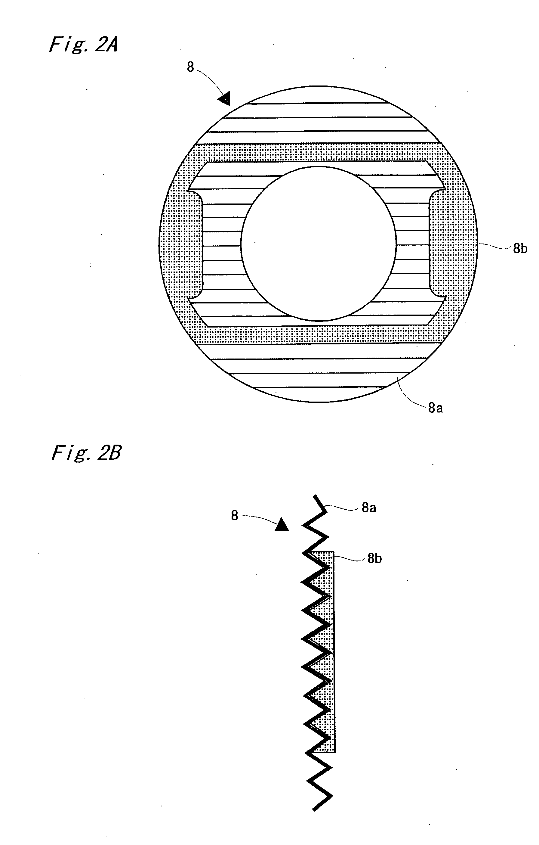
[0007] The plate member may be constructed by affixing a first member having flexibility and a second member which is uneasy to deform. Consequently, the durability can be significantly improved, as compared with that in a case where the plate member is composed of only the first member having flexibility.
[0009] In the projection type video display having such a configuration, the plate member may be externally fitted in the body of the projection lens, and the plate member may be connected to a movable member on which the projection lens is mounted in the lens shift mechanism. In such a configuration, the plate member can be prevented from being undesirably turned and moved.
[0010] Alternatively, in the projection type video display having such a configuration, the plate member may be externally fitted in the body of the projection lens, and there may be further provided a restraining member for restraining the movement of the plate member by touching the plate member. In such a configuration, the plate member is simply externally fitted in the body of the projection lens. As a result, the assembling work is significantly easy.

Problems solved by technology

However, the large clearance between the projection lens and the aperture of the front cover not only loses design but also allows dust to easily enter a frame of the projector.

Method used


Image

  • Projection type video display
  • Projection type video display
  • Projection type video display

Examples


Embodiment Construction

[0023] A projection type video display according to an embodiment of the present invention will be described on the basis of FIGS. 1 to 8. First, an optical system for a liquid crystal projector is illustrated. FIG. 8 is a diagram illustrating an optical system for a three-panel color liquid crystal projector. A light emitter in a light source 101 is composed of a ultra-high pressure mercury lamp, a metal halide lamp, a xenon lamp, or the like, and its irradiated light is emitted after being changed into parallel lights by a parabolic reflector, and is introduced into an integrator lens 102

[0024] The integrator lens 102 is composed of pairs of groups of lenses, and each of the pairs of lenses introduces the light emitted from the light source 101 into the whole surface of liquid crystal light valves 111, 112, and 113. The light which has passed through the integrator lens 102 is introduced into a first dichroic mirror 103.

[0025] The first dichroic mirror 103 transmits light in a re...


PUM

PropertyMeasurementUnit
angleaaaaaaaaaa
angleaaaaaaaaaa
flexibilityaaaaaaaaaa

Abstract

A doughnut-shaped dust-proof plate is externally fitted in the body of the projection lens. The dust-proof plate comprises a first member which is flexible like rubber and a second member made of plastic which is uneasy to deform. The second member is made lower in a vertical direction (lengthwise) than the first member, thereby making it possible to allow deformation at an upper end and a lower end of the first member. On the other hand, the second member is made long in a horizontal direction (crosswise). A longitudinal portion of the second member is set to have such a length that it can come into contact with a lower wall of the frame of the liquid crystal projector even if the projection lens is positioned at the uppermost position and can come into contact with an upper wall of the frame even if the projection lens is positioned at the lowermost position in a state where the dust-proof plate is obliquely turned. Therefore, the dust-proof plate is prevented from being turned at an angle of 90 degrees.

Description

BACKGROUND OF THE INVENTION Field of the Invention [0001] The present invention relates to a projection type video display comprising a lens shift mechanism. [0002] Examples of a projection type video display include a liquid crystal projector. A known liquid crystal projector comprises a lens shift mechanism for moving a projected video up and down with its main body kept immovable and preventing the projected video from having a trapezoidal shape (JP-A-09-138377). SUMMARY OF THE INVENTION [0003] In a lens shift mechanism, a relatively large lens shift width can be ensured in a vertical direction (lengthwise) or a horizontal direction (crosswise). For this purpose, a large clearance must be ensured between a projection lens and an aperture of a front cover in a liquid crystal projector in correspondence with the lens shift width. However, the large clearance between the projection lens and the aperture of the front cover not only loses design but also allows dust to easily enter a ...

Claims


Application Information

Patent Timeline
Patent Type & Authority Applications(United States)
IPC IPC(8): G02F1/13G02B7/02G02F1/1335G03B21/00G03B21/14H04N5/74
CPCH04N9/3141H04N5/7441
Inventor GISHI, HIROMITSU
Owner SANYO ELECTRIC CO LTD
Learn More