Miniature optical free space transceivers

a free space transceiver and miniature technology, applied in the field of free space optical communication, can solve the problems of difficult to overcome the technical difficulties of free space optical transceivers, the scattered light beam emitted from the transmitters, and the general cost of laying optical fibers in dense metropolitan areas, so as to achieve the effect of outweighing optical costs

Inactive Publication Date: 2005-02-10
RAD OP
View PDF10 Cites 21 Cited by
  • Summary
  • Abstract
  • Description
  • Claims
  • Application Information

AI Technical Summary

Benefits of technology

[0013] A general aspect of some embodiments of the present invention relates to using an optical transceiver, including a transmitter and a receiver adjacent to each other, which was designed for use with a fiber optic pair, for free space transmission. The use of transceivers designed for a fiber, for free space transmission, allows use of standard small and cheap elements, which are widely available. This advantage has been found by the inventor of the present invention, to outweigh the costs of optically adapting the beams of the transceiver for free space transmission.
[0015] In some embodiments of the invention, optical elements, such as lenses and / or mirrors, positioned between the transmission and reception ports and the reception collecting lens, expand the effective distance between transmission and reception beams entering or exiting the ports, so that the beams do not overlap.
[0016] Alternatively, a collection lens that has a small transmission window with different optical properties from the rest of the collection lens, is used to allow the transmitted beam to be handled differently from the received beam.

Problems solved by technology

The cost of laying optical fibers in dense metropolitan areas is generally enormous if not prohibitive.
Free space optical transceivers, however, need to overcome some technical problems.
In addition, the light beam emitted from the transmitter is frequently scattered by dust or fog or is randomly refracted by turbulent air and / or random temperature fluctuations.
The cost and complexity of free space optic transceivers is therefore relatively high, and attempts have been made to reduce the cost.

Method used


Image

  • Miniature optical free space transceivers
  • Miniature optical free space transceivers
  • Miniature optical free space transceivers

Examples


Embodiment Construction

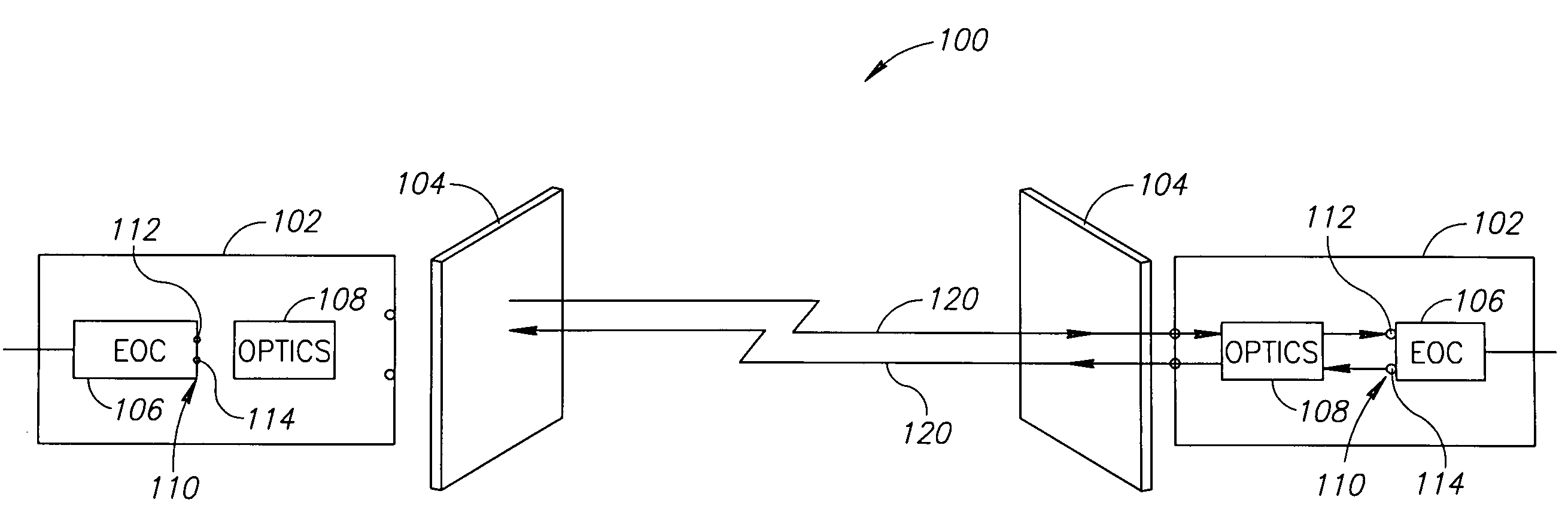
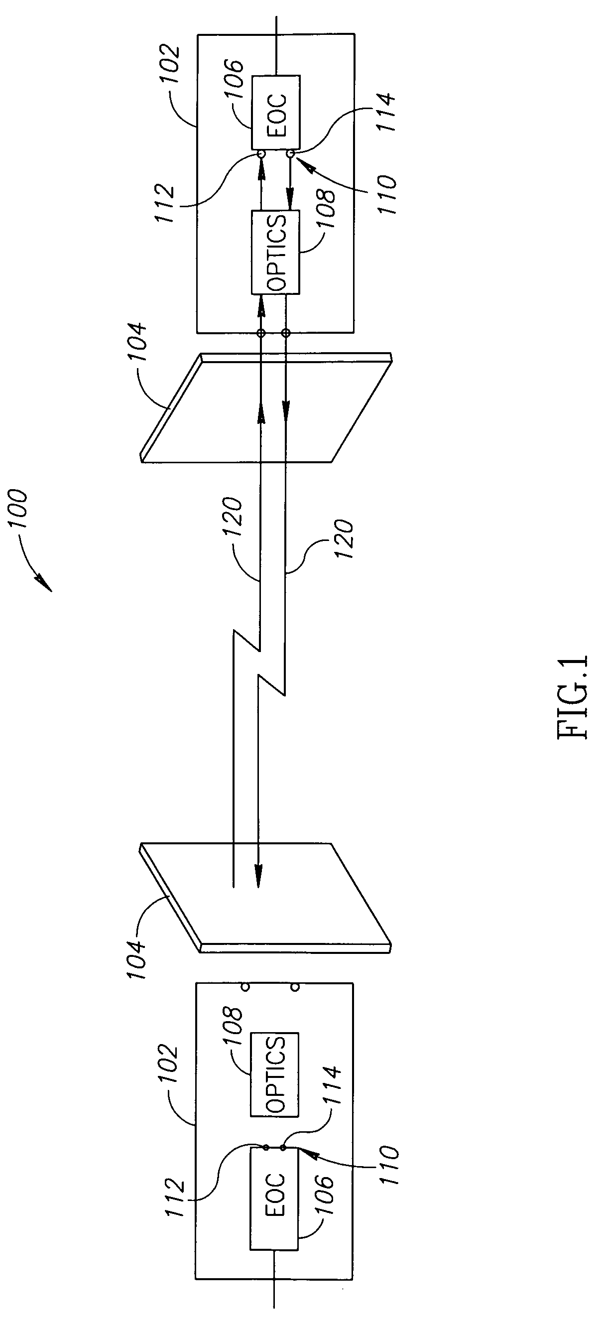
[0035]FIG. 1 is a schematic illustration of an optical free-space transmission system 100, in accordance with an exemplary embodiment of the present invention. System 100 comprises a pair of optical data transceivers 102, positioned in line of sight with each other. Transceivers 102 are optionally mounted on respective windows 104 in adjacent or otherwise neighboring buildings. Each of transceivers 102 transmits a modulated light beam 120, which carries data, to the other transceiver. Light beams 120 are substantially parallel so that the transceivers are easily aligned relative to each other for both transmission and reception. Transmitted and received light beams 120 may include light of the same wavelength or of different wavelengths. Each transceiver 102 optionally includes an electro-optical conversion unit (EOC) 106, adapted to generate a modulated light beam from a first electrical signal and to convert a modulated light beam into a second electrical signal, as described belo...


PUM


Abstract

A free space optical transceiver including an electro-optical conversion unit having a transmission port and a reception port, with centers separated by a first distance; an optics unit adapted to lead a light beam from the atmosphere to the reception port and to lead a light beam from the transmission port to the atmosphere, wherein the optics unit includes at least one optical element having a diameter larger than the first distance.

Description

CROSS REFERENCE TO RELATED APPLICATIONS [0001] This application claims the benefit from U.S. provisional application No. 60 / 492,760 filed on Aug. 5, 2003 by the same inventor.FIELD OF THE INVENTION [0002] The present invention relates to free-space optical communications. BACKGROUND OF THE INVENTION [0003] One method used for communicating data is transmission of modulated light beams. In many cases, the light beams are transmitted through optical fibers that provide a low attenuation medium for light beams, such that the light beams can be forwarded over large distances without being regenerated. When two-way transmission is required, two optical fibers are generally used. A terminal, including at least one pair of a transmitter and a receiver, is positioned at each end of the pair of fibers. Such terminals frequently handle many pairs of fibers. In order to keep the terminals as small as possible, the transmitters and receivers are packed as close as possible to each other. In an ...

Claims


Application Information

Patent Timeline
Patent Type & Authority Applications(United States)
IPC IPC(8): H04B10/00H04B10/10
CPCH04B10/1127
Inventor HABER, ILAN
Owner RAD OP
Why Eureka
Try Eureka