Bearing and gear unit for wind turbines

a technology of bearings and gear units, applied in the direction of bearings, toothed gearings, shafts, etc., can solve the problem of power transmission via slip rings, and achieve the effect of facilitating the many poles relatively inexpensively and small stiffness

Inactive Publication Date: 2016-06-02
GROENAGER JENS
View PDF0 Cites 6 Cited by
  • Summary
  • Abstract
  • Description
  • Claims
  • Application Information

AI Technical Summary

Benefits of technology

[0003]The combined bearing and gear unit according to the invention also saves the central rotor shaft as PTO from the individual rollers of the only remaining bearing provide the equivalent of traditional first-stage gearing. One embodiment is to attach many relatively small mass-produced generators, one on each PTO to facilitate the many poles relatively inexpensively. If the bearings 6 and 7 of FIGS. 1 to 6 for the individual roller shafts are firmly rooted in the nacelle the upper quarter must be able to support the whole weight of the rotor attached to the outer ring 2. Otherwise, a free counter-rotating inner ring as shown in FIG. 6, can transfer half of this weight to the lower rollers when the rollers are fixated to the nacelle with a smaller stiffness than the stiffness of the inner ring. Alternatively, a fixed inner ring can support the total weight of the rotor so that the bearings 6 and 7 between the rings 1 and 2 of FIG. 1 only have to resist the outward pressing force from the conical rollers. A drawback of this embodiment is that the power must then be transmitted via slip rings because the assembly of rollers between the rings rotate at half speed and the gearing is also half of the aforementioned alternatives.

Problems solved by technology

A drawback of this embodiment is that the power must then be transmitted via slip rings because the assembly of rollers between the rings rotate at half speed and the gearing is also half of the aforementioned alternatives.

Method used


Image

  • Bearing and gear unit for wind turbines
  • Bearing and gear unit for wind turbines
  • Bearing and gear unit for wind turbines

Examples


Embodiment Construction

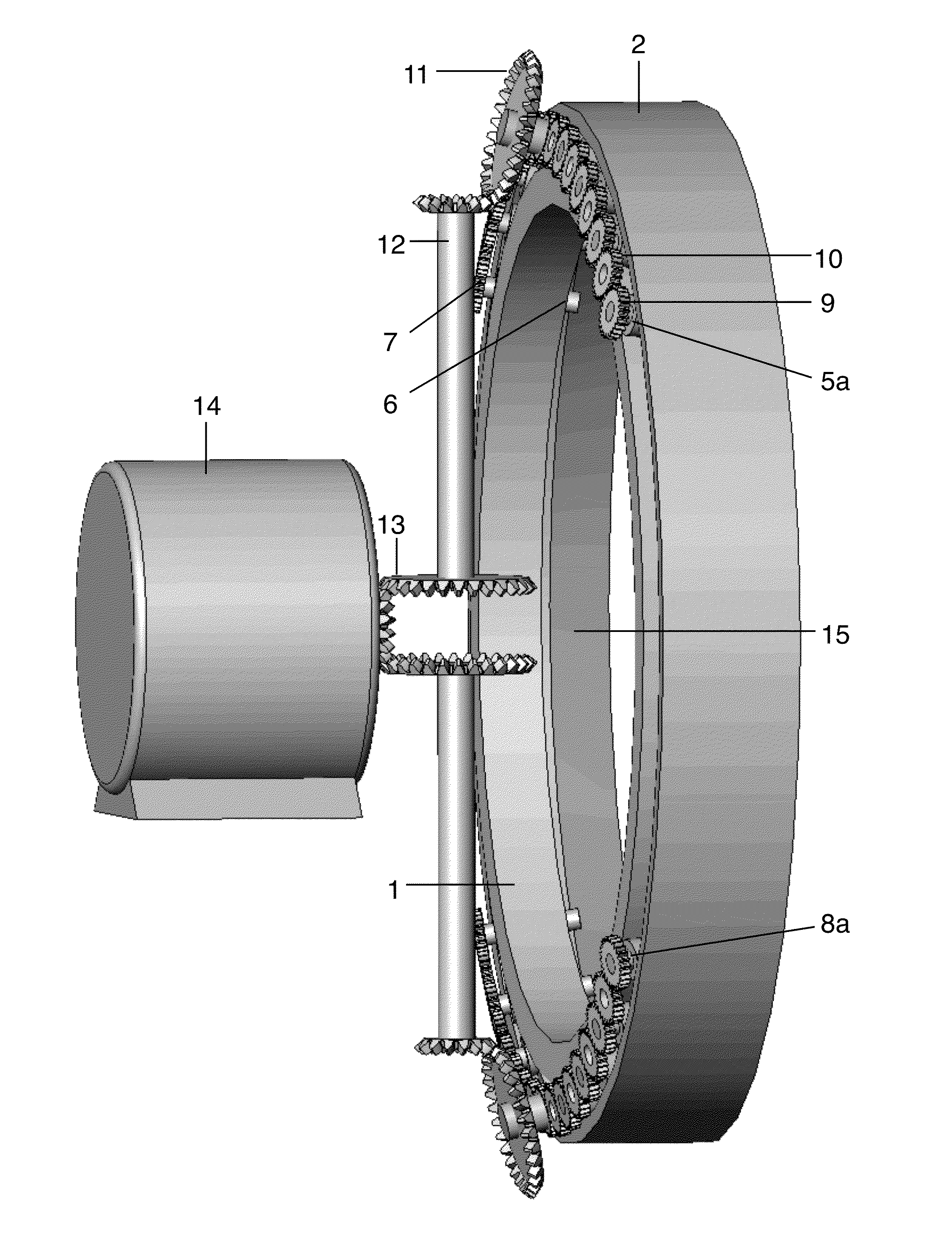
[0015]In FIGS. 1, 1 and 2 are the inner and outer ring where 1 for a 7MW turbine has a distance of two and a half meters to the bearing center axis in the direction of the wind. 4 is the intermediate ring spacer to which the rollers 5 are attached with bearings 6 and 7.

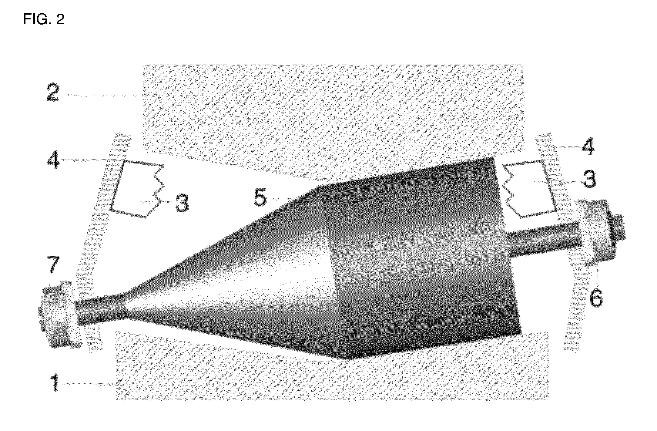
[0016]FIG. 2 is the corresponding radial section along A-A of FIG. 1 where also a part of the load bearing connection 3 between the two opposed portions of the spacer ring 4 is shown behind roller 5

[0017]In FIG. 3, the load bearing connection 3 is formed as a central freewheeling ring between rings 1 and 2 to which the shafts 4 of the opposing rollers, gears and generators 20 are rigidly fixed.

[0018]FIG. 4 shows a rotationally symmetric section through two opposing roller gear generator units 20 along their axis of symmetry 19. The axial roller bearing 7 supplies the necessary back pressure for the conical roller 5, whose second support is the bearing 6. Concentric with the left extension of 5 with the same shading th...


PUM


Abstract

The economic efficiency of wind turbines improves by upscaling but the weight to strength ratio deteriorates. This is especially true for the large shaft and bearing of the rotor, the gearbox and the generator. Solutions to this was the gearless generator, getting heavy because the amount of magnetic material is inversely proportional to speed, or several smaller generators adapted to the wind on a distribution gear as shown in references (1), (2) and (3). The large roller bearing of the rotor has relatively large bearing clearance so only the top or lower rollers bear the entire weight of the rotor and thus must be dimensioned relatively large. The present invention spreads the load on the support bearing to more rollers and to smaller faster running and thereby lighter generators. It has the rotor attached to the outer ring, each roller rotatably mounted to the nacelle and the inner ring free wheeling. The outer and inner rings are relatively stiffer than the rotatable fixation of the upper rollers to the nacelle, so that the upper rollers flex slightly down under the weight of the rotor allowing some of the force of gravity to be transferred to the inner ring and on to the bottom relatively stiff journalled rollers. Gear teeth can be used to transfer torque to all rollers, or the inner ring pressed against the side rollers, or the conical rollers can be pressed dynamically in between the outer and inner ring with relatively constant force. This is shown in FIGS. 1 and 6 in perspective and FIG. 2 and FIG. 3, in radial section. The relatively small roller shafts can now be used as PTO with gear ratio bearing diameter to roller diameter. The cost of the extra bearings for each roller is offset by savings in the usual center shaft and gear. Also, the friction from the edge of the outer or inner ring to keep the large rollers in place is missing. These benefits are especially important for wind turbines with heavy hub, axle and gear on a tall tower, and large wing rotor bearing clearance causing inappropriate vibrations of the long components. With no central hub shaft, gear and generator in the nacelle center there is space for force carrying structures as strong as the top of the tower to a point on the centre line of the rotor in front of it. To this a bearing for sustaining the varying moments of the wind can be affixed so the weight carrying bearing and gear unit can be designed cylindrical; or stays can be continued to other tower elements achieving a tower structure with significantly lower weight and higher natural frequency than usual wind moment influenced single column towers.

Description

BACKGROUND OF THE INVENTION[0001]Concurrent with wind turbines scaling up to MW class the weight of the nacelle has gone from approximately twice the rotor weight to triple or quadruple. This because the mass forces in the cube of the wing length dominates over the wind forces in the second power thereof. The relatively large components in the nacelle, that must sustain these forces also have a comparatively poorer weight to strength ratio. For example, the weight of the large massive hub shaft is proportional to the cube of its radius while forces are mainly absorbed in its surface proportional to the square thereof. The same conditions apply to the large central input gear wheel that also predominantly absorbs forces in its periphery thus not utilizing its central mass. Consequently there is an opportunity to save mass, which in prior art was just there; not used for resisting forces and amounted to roughly a quarter of the nacelle weight. The purpose of the present invention is t...

Claims


Application Information

Patent Timeline
Patent Type & Authority Applications(United States)
IPC IPC(8): F03D11/02F16H3/30
CPCF03D11/0008F05B2240/50F05B2260/40311F16C19/364F16C19/386F16C19/52F16C33/526F16C2300/14F16C2360/31F16H13/06F16H37/02F03D15/00F03D80/70Y02E10/72
Inventor GROENAGER, JENS
Owner GROENAGER JENS
Why Eureka
Try Eureka