Bicycle sprocket

a sprocket and bicycle technology, applied in the field of bicycle sprockets, can solve the problems of difficult to maintain a high rigidity and the manufacturing process becomes relatively complex, and achieve the effects of preventing looseness, improving the yield of sprocket ring parts, and improving the manufacturing process

Inactive Publication Date: 2005-02-10
SHIMANO INC
View PDF15 Cites 62 Cited by
  • Summary
  • Abstract
  • Description
  • Claims
  • Application Information

AI Technical Summary

Benefits of technology

[0008] One object of the present invention is to provide a bicycle sprocket that is constructed of two different materials that is light weight, maintains rigidity, prevents looseness or play between the two materials, and can be fabricated with a simplified manufacturing process.
[0021] With the present invention, since the sprocket ring part and the fastening part are fixed together by molding the fastening part integrally to both lateral faces of the sprocket ring part, looseness can be prevented and a high rigidity can be maintained between the sprocket ring part and the fastening part. Additionally, the manufacturing process can be simplified because it is not necessary to provide a crimping step for installing crimp pins and crimping them. Furthermore, the weight of the sprocket can be reduced because the fastening part is made of a synthetic resin.

Problems solved by technology

Thus, it is difficult to maintain a high rigidity.
Furthermore, the manufacturing process becomes relatively complex because a step is necessary during which the crimp pins are inserted into the two members and then crimped.

Method used


Image

  • Bicycle sprocket
  • Bicycle sprocket
  • Bicycle sprocket

Examples


Embodiment Construction

[0034] Selected embodiments of the present invention will now be explained with reference to the drawings. It will be apparent to those skilled in the art from this disclosure that the following descriptions of the embodiments of the present invention are provided for illustration only and not for the purpose of limiting the invention as defined by the appended claims and their equivalents.

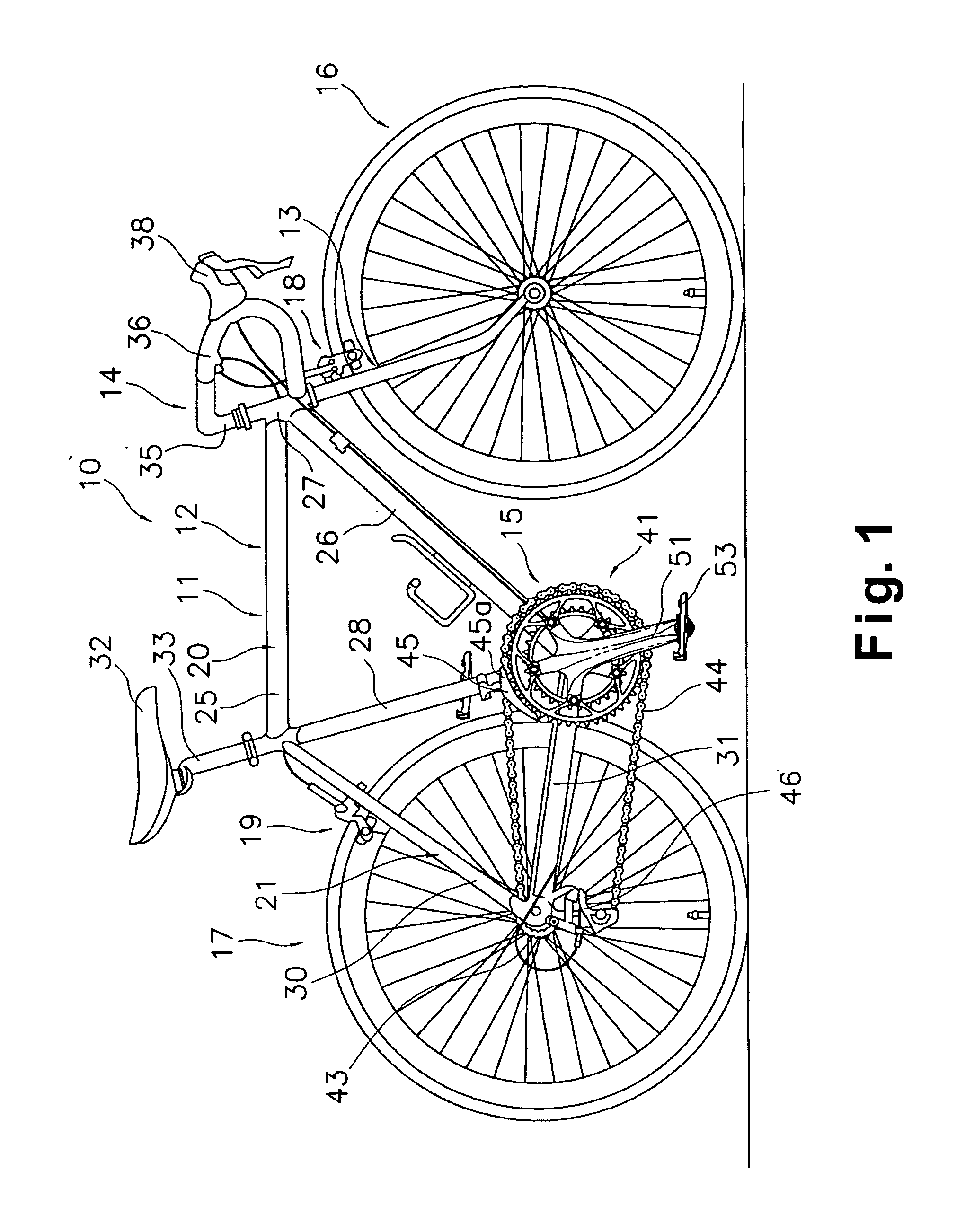
[0035] Referring initially to FIG. 1, a bicycle 10 is illustrated in accordance with a first embodiment of the present invention. As an example of a bicycle 10 that employs an embodiment of the present invention, FIG. 1 shows a road bike 10 having a drop-type handlebar unit 14. The road bike 10 has a diamond-shaped frame 11 that serves as the framework of the bicycle body. The frame 11 has a frame body 12 and a front fork 13. The front fork 13 is supported on a front part of the frame 12 such that it can rotate freely about an axis that is tilted slightly from vertical. The lower part of the fron...


PUM


Abstract

A bicycle crank is provided with a bicycle sprocket that includes a sprocket ring part and a fastening part. The sprocket ring part includes first and second lateral side surfaces with a plurality of sprocket teeth arranged around an outer periphery thereof. The sprocket ring part is constructed of metal. The fastening part is adapted to be fixedly coupled to a rotational drive unit such as the right crank arm of a bicycle. The fastening part is constructed of synthetic resin material that is at least partially molded integrally around the first and second lateral side surfaces of the sprocket ring part at an area located radially inwardly the sprocket teeth. Preferably, the sprocket ring part is provided with an anchor structure to facilitate non-rotatable engagement with fastening part. Preferably, the anchor structure includes through holes and / or protrusion and depression arrangement.

Description

BACKGROUND OF THE INVENTION [0001] 1. Field of the Invention [0002] The present invention generally relates to a bicycle sprocket. More specifically, the present invention relates to a bicycle sprocket configured to be mounted to a rotational drive unit such as a crank of a bicycle and to have a bicycle (drive-purpose) chain wrapped around the outside circumference thereof. [0003] 2. Background Information [0004] A bicycle is generally provided with a drive unit or drive train having front and rear sprockets and a chain wrapped around the sprockets. The front sprocket(s) is provided on the gear crank of the bicycle and the rear sprocket(s) is provided on the free hub of the bicycle. This type of bicycle sprocket is made of such materials as the aluminum having the designation A2014P under the standard JIS H4000 (category) or the iron having the designation SPCC under the standard JIS G3141 (category). When a plurality of sprockets are mounted to the gear crank and free hub in order ...

Claims


Application Information

Patent Timeline
Patent Type & Authority Applications(United States)
IPC IPC(8): B62K19/16B62M3/00B62M9/10F16H55/06F16H55/30
CPCB62K19/16F16H2055/065F16H55/06B62M9/10B62M9/105
Inventor NONOSHITA, TETSUNISHIMOTO, YUSUKE
Owner SHIMANO INC
Why Eureka
Try Eureka