Low cost electrical stimulation and shock devices manufactured from conductive loaded resin-based materials

a technology of conductive loaded resin and low cost, which is applied in the direction of electrotherapy, external electrodes, electrotherapy, etc., can solve problems such as actual electrical shock transmission, and achieve the effect of effective electrical stimulator or shock devi

Inactive Publication Date: 2005-02-10
INTEGRAL TECHNOLOGY INC
View PDF12 Cites 29 Cited by
  • Summary
  • Abstract
  • Description
  • Claims
  • Application Information

AI Technical Summary

Benefits of technology

[0010] A principal object of the present invention is to p

Problems solved by technology

More aggressive application of electrical stimulus

Method used


Image

  • Low cost electrical stimulation and shock devices manufactured from conductive loaded resin-based materials
  • Low cost electrical stimulation and shock devices manufactured from conductive loaded resin-based materials
  • Low cost electrical stimulation and shock devices manufactured from conductive loaded resin-based materials

Examples


embodiment 20

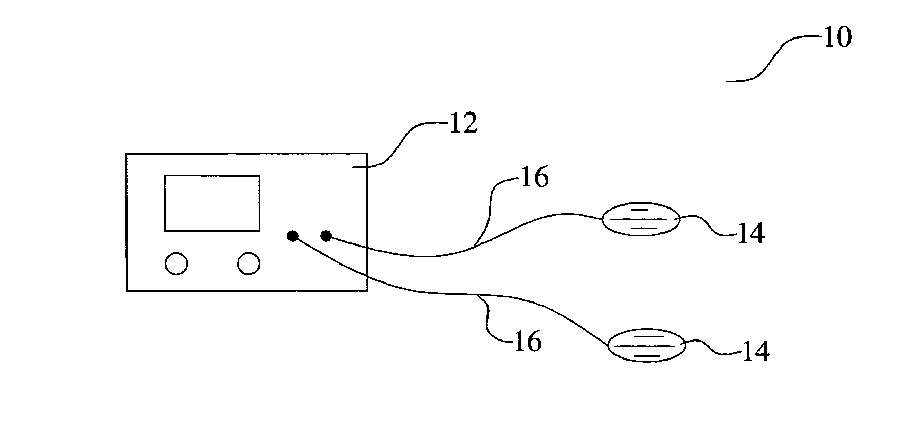
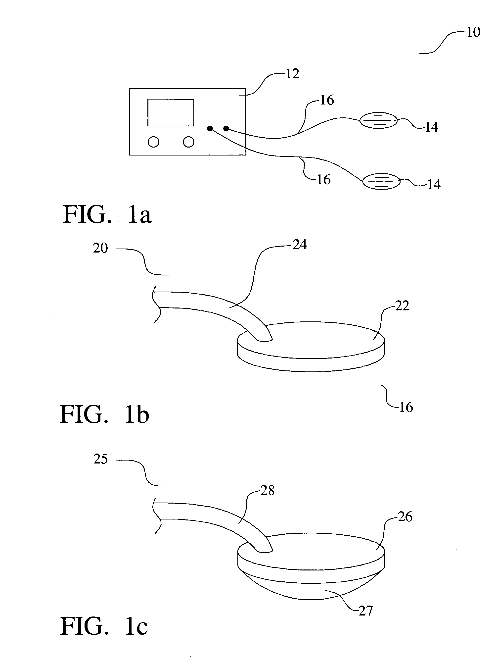
[0045] Referring now to FIG. 1b, in a second preferred embodiment 20 of the present invention, the conductive paddles 22 are connected to the energy source via conductive cables 24. In one embodiment, both the conductive cables 24 and the paddles 22 comprise the conductive loaded resin-based material of the present invention. The low resistivity of the conductive loaded resin-based network allows the electrical signal to be transmitted through the cables 24 with little loss. Further, in another embodiment, the cables 24 and the paddles 22 are molded as a single unit. In yet another embodiment, the cables 24 and the paddles 22 are molded separately and then joined together using, for example, an ultrasonic welding process. The conductive loaded resin-based cable 24 is preferably covered with a non-conductive material such as a non-conductive base resin material.

[0046] Alternatively, the cables 24 may comprise a more traditional conductor such as a metal wire or group of wires. In thi...

embodiment 140

[0051] Referring now to FIG. 8, a sixth preferred embodiment 140 of the present invention is illustrated. In this case, a cattle prod device 140 is formed of the conductive loaded resin-based material. In this case, the electrodes 146 of the prod 140 are formed of the conductive loaded resin-based material. The unique network of micron conductive fibers and / or powders in the polymeric base provides multiple points on the surface of each electrode 146 for electrical charge to exit the electrode 146, to enter the animal's body, and to then be discharged to the ground on which the animal stands. In one embodiment, a battery / control pack is housed within the handle 142. Activation of the prod trigger 144 generates a high voltage potential in the circuit that is transmitted through the shaft 148 to the prod electrodes 146.

[0052] In one embodiment, conductive circuit lines between the battery / control pack in the handle 142 and the electrodes 146 also comprises the conductive loaded resin-...


PUM


Abstract

Electrical stimulators and shocking devices are formed of a conductive loaded resin-based material. The conductive loaded resin-based material comprises micron conductive powder(s), conductive fiber(s), or a combination of conductive powder and conductive fibers in a base resin host. The percentage by weight of the conductive powder(s), conductive fiber(s), or a combination thereof is between about 20% and 50% of the weight of the conductive loaded resin-based material. The micron conductive powders are formed from non-metals, such as carbon, graphite, that may also be metallic plated, or the like, or from metals such as stainless steel, nickel, copper, silver, that may also be metallic plated, or the like, or from a combination of non-metal, plated, or in combination with, metal powders. The micron conductor fibers preferably are of nickel plated carbon fiber, stainless steel fiber, copper fiber, silver fiber, or the like.

Description

[0001] This Patent Application claims priority to the U.S. Provisional Patent Application 60 / 492,348, filed on Aug. 4, 2004, which is herein incorporated by reference in its entirety. [0002] This Patent Application is a Continuation-in-Part of INT01-002CIP, filed as U.S. patent application Ser. No. 10 / 309,429, filed on Dec. 4, 2002, also incorporated by reference in its entirety, which is a Continuation-in-Part application of docket No. INT01-002, filed as U.S. Pat. application Ser. No. 10 / 075,778, filed on Feb. 14, 2002, which claimed priority to U.S. Provisional Patent Applications Ser. No. 60 / 317,808, filed on Sep. 7, 2001, Ser. No. 60 / 269,414, filed on Feb. 16, 2001, and Ser. No. 60 / 268,822, filed on Feb. 15, 2001.BACKGROUND OF THE INVENTION [0003] (1) Field of the Invention [0004] This invention relates to electrical stimulation and shock devices and, more particularly, to electrical stimulation and shock devices molded of conductive loaded resin-based materials comprising micr...

Claims


Application Information

Patent Timeline
IPC IPC(8): A61N1/04
CPCA61N1/0452A61N1/0456A61N1/0492A61N1/0484A61N1/046
Inventor AISENBREY, THOMAS
Owner INTEGRAL TECHNOLOGY INC
Why Eureka
Try Eureka