
System for wide frequency dynamic nanomechanical analysis

Active Publication Date: 2005-02-17
BRUKER NANO INC
View PDF40 Cites 17 Cited by
  • Summary
  • Abstract
  • Description
  • Claims
  • Application Information

AI Technical Summary

Benefits of technology

One objective of the present invention is to overcome the parasitic resonance in conventional dynamic nanomechanical analysis systems, which occurs as low as a few hundred hertz, and expands the dynamic nanomechanical measurements into the megahertz range. Another objective is to enable dynamic nanomechanical analysis in small sized samples, such as mono molecular or atomic layer materials on a cantilever probe. Another objective of the invention is to perform localized dynamic nanomechanical measurements so that the sample interaction with the applied stresses is restricted into the region as small as tens of nanometers. Yet another objective is to apply forces of different directions concurrently or intermittently so that the material under study can be examined not only in multiple frequencies but also multiple force components. An advantage of the present invention is that it enables atomic force imaging and localized dynamic nanomechanical measurements to be performed during the same procedure in a single instrument. Another advantage of the present invention is that it enables a determination of mechanical spectra in terms of both shear force and compressive force to be performed in-situ at the same localized location of a sample.

Problems solved by technology

The over-powered modulation of the sample holder shares the same problem.

Method used


Image

  • System for wide frequency dynamic nanomechanical analysis
  • System for wide frequency dynamic nanomechanical analysis
  • System for wide frequency dynamic nanomechanical analysis

Examples


Embodiment Construction

The present invention relates generally to the field of determination of the dynamic mechanical properties of materials. More particularly, the present invention relates to a system that utilizes forces applied at frequencies that are swept over a wide frequency range that includes frequencies higher than a resonance frequency of the system in order to perform localized dynamic nanomechanical analysis of small samples, films and surfaces.

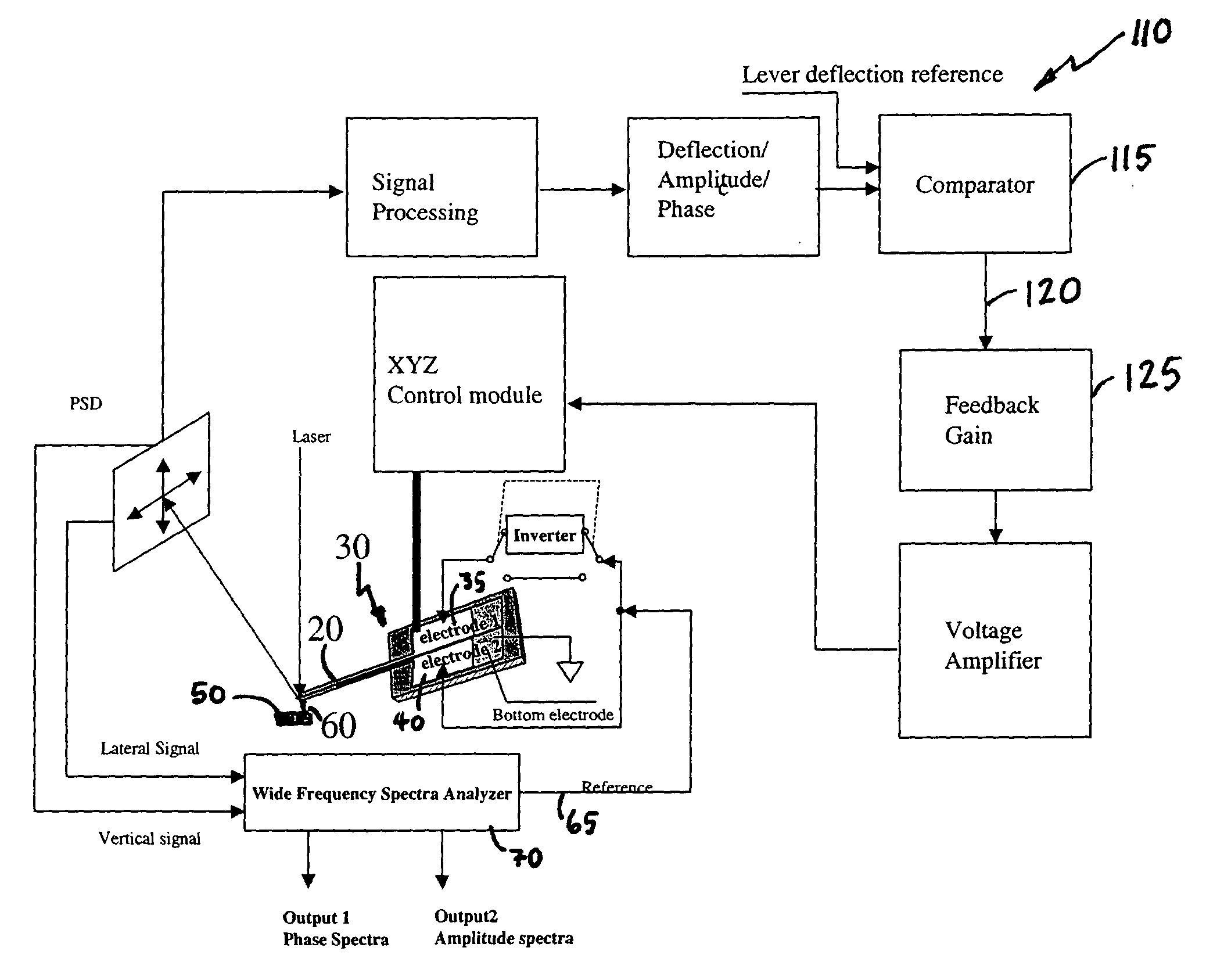
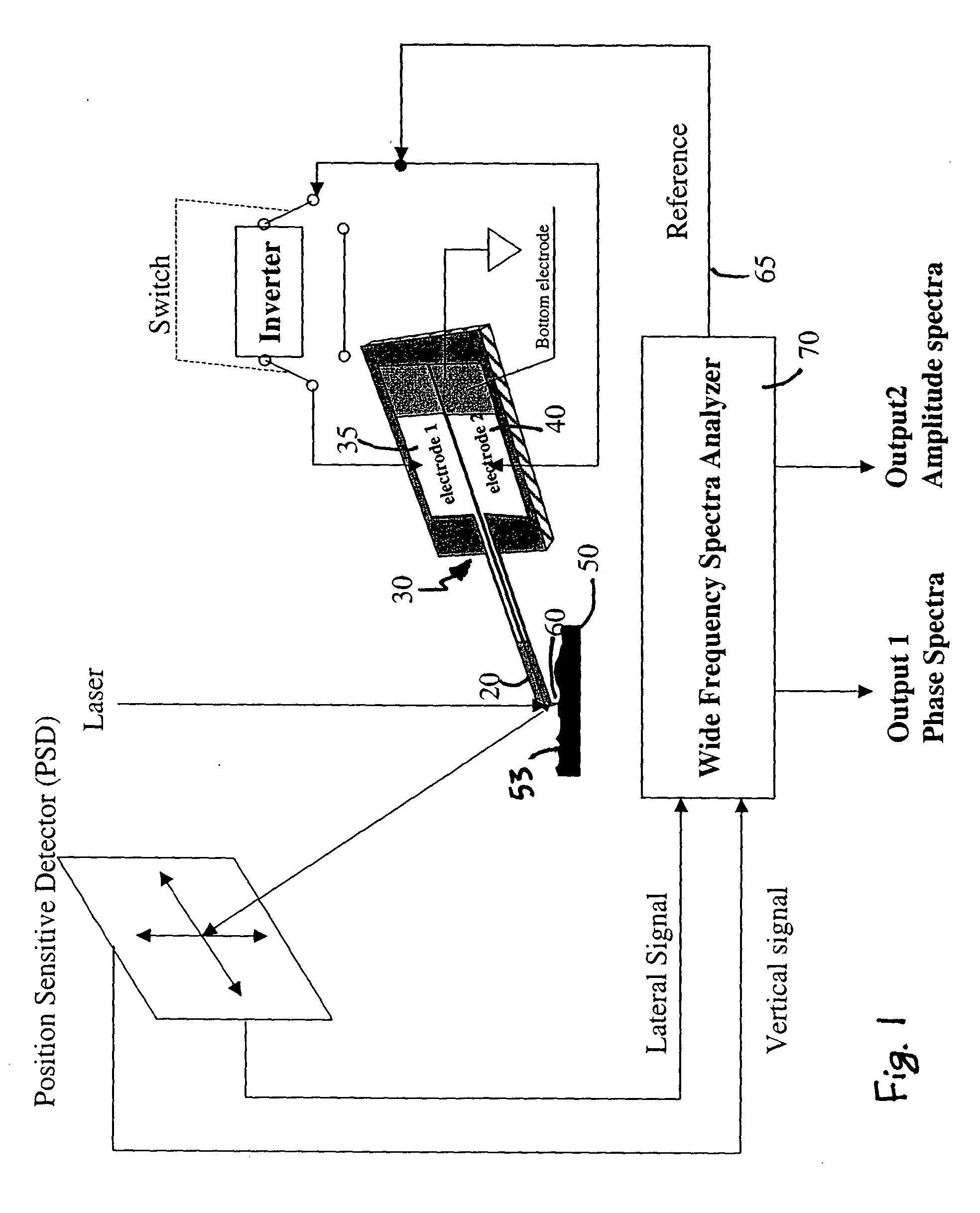
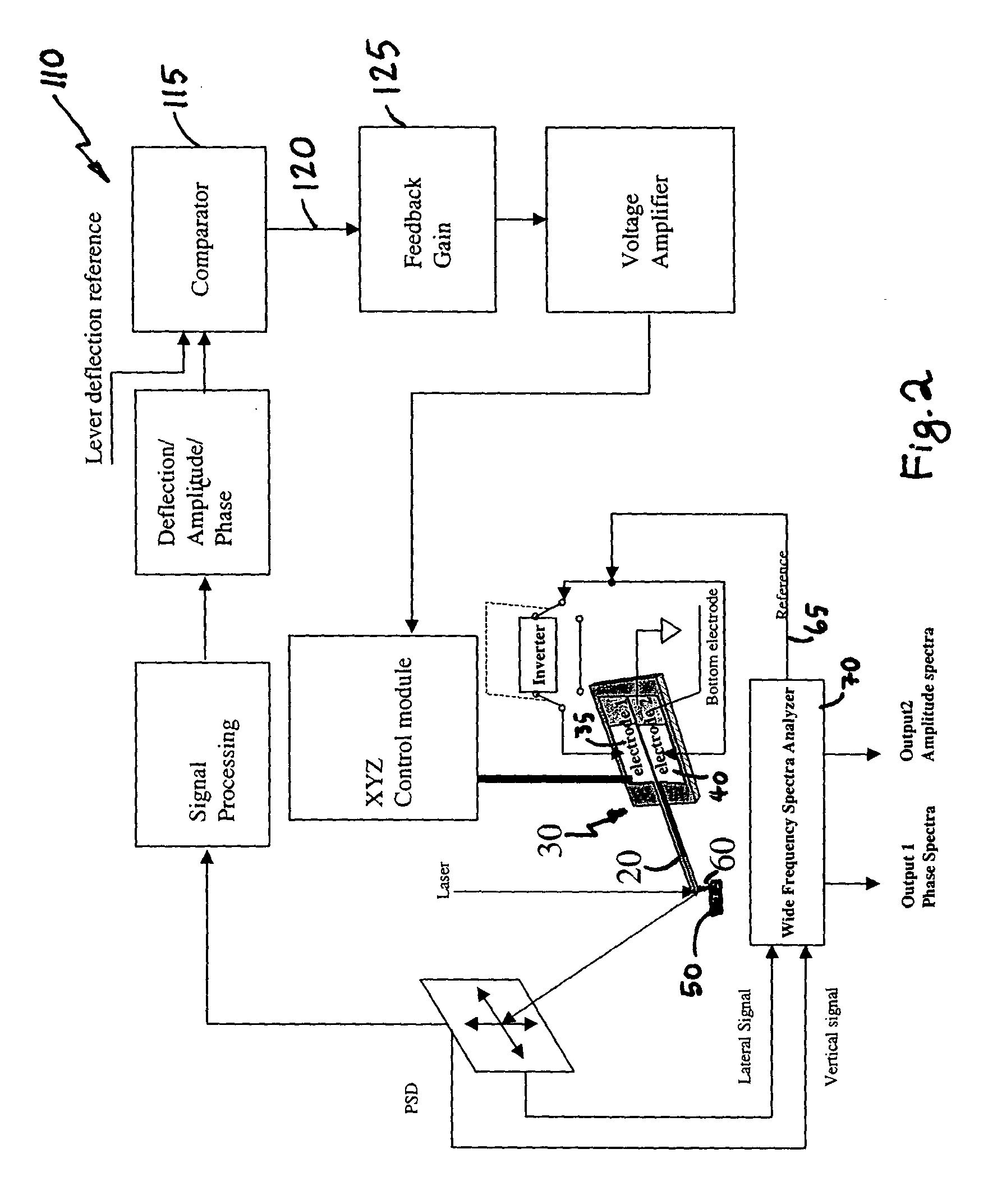
FIG. 1 is a schematic showing the principle of operation of a preferred embodiment of the present invention. A cantilever 20 with active elements 30, such as, for example, a piezo electric layer sandwiched between top 35 and bottom 40 electrodes is used to drive the front part of the lever 20, interacting with the sample 50 at the tip 60 which is in contact with the sample 50. The top electrodes 35 are electrically separated into two areas. A periodic signal 65 from a spectra analyzer 70 is applied to top electrodes 35 and 40 either in phase or ou...


PUM


Abstract

Dynamic nanomechanical analysis of a sample is performed by using a cantilever probe that interacts with the sample using a force applied across a wide range of frequencies that includes frequencies greater than 300 Hz. The motion of the cantilever probe is detected in response to the applied force over the range of frequencies and analyzed over at least a portion of the wide range of frequencies to determine a mechanical response of the sample, preferably including quality factor and modulus of the sample. The analysis of the motion of the cantilever probe is preferably performed in terms of amplitude, phase, and frequency of both the probe and the sample and preferably, where the applied force is analyzed to determine both a real and an imaginary modulus of a mechanical response of the sample. Preferably, the force is applied so as to produce a minimum of phase and amplitude response variation in the absence of the sample. Furthermore the motion of the cantilever can be flexural or torsional and combinations thereof.

Description

FIELD OF THE INVENTION The present invention relates generally to the field of determination of the dynamic mechanical properties of materials. More particularly, the present invention relates to a system that utilizes forces applied at frequencies that are swept over a wide frequency range that includes frequencies higher than the fundamental resonance frequencies of conventional nanomechanical analysis systems in order to perform localized dynamic nanomechanical analysis of small samples, films and surfaces. BACKGROUND OF THE INVENTION The quantities determining mechanical response of materials or objects to external force are generally referred as elastic constants. Measurements of elastic response can be performed statically and dynamically. In static measurement the deformation of material at the instance of application of external force indicates compliance of the materials. The amount of deformation is determined by elastic modulus that is a fundamental property of the mate...

Claims


Application Information

Patent Timeline
IPC IPC(8): G01N3/00G01N3/02G01Q60/38G01Q70/04
CPCB82Y35/00G01N3/00G01N2203/0051G01Q70/04G01N2203/0094G01N2203/0286G01Q60/38G01N2203/0075
Inventor SU, CHANMIN QUANMINMAGONOV, SERGEI
Owner BRUKER NANO INC
Learn More