

Reamer apparatus for ground boring machine
a technology of reamer apparatus and ground boring machine, which is applied in mechanical apparatus, shaft equipment, directional drilling, etc., can solve the problems of affecting the operation of the machine, so as to prevent the increase of the drawing resistance of the pipe, eliminate the obstruction, and improve the effect of flexibility
- Summary
- Abstract
- Description
- Claims
- Application Information
AI Technical Summary
Benefits of technology
Problems solved by technology
Method used
Image

Examples
Embodiment Construction
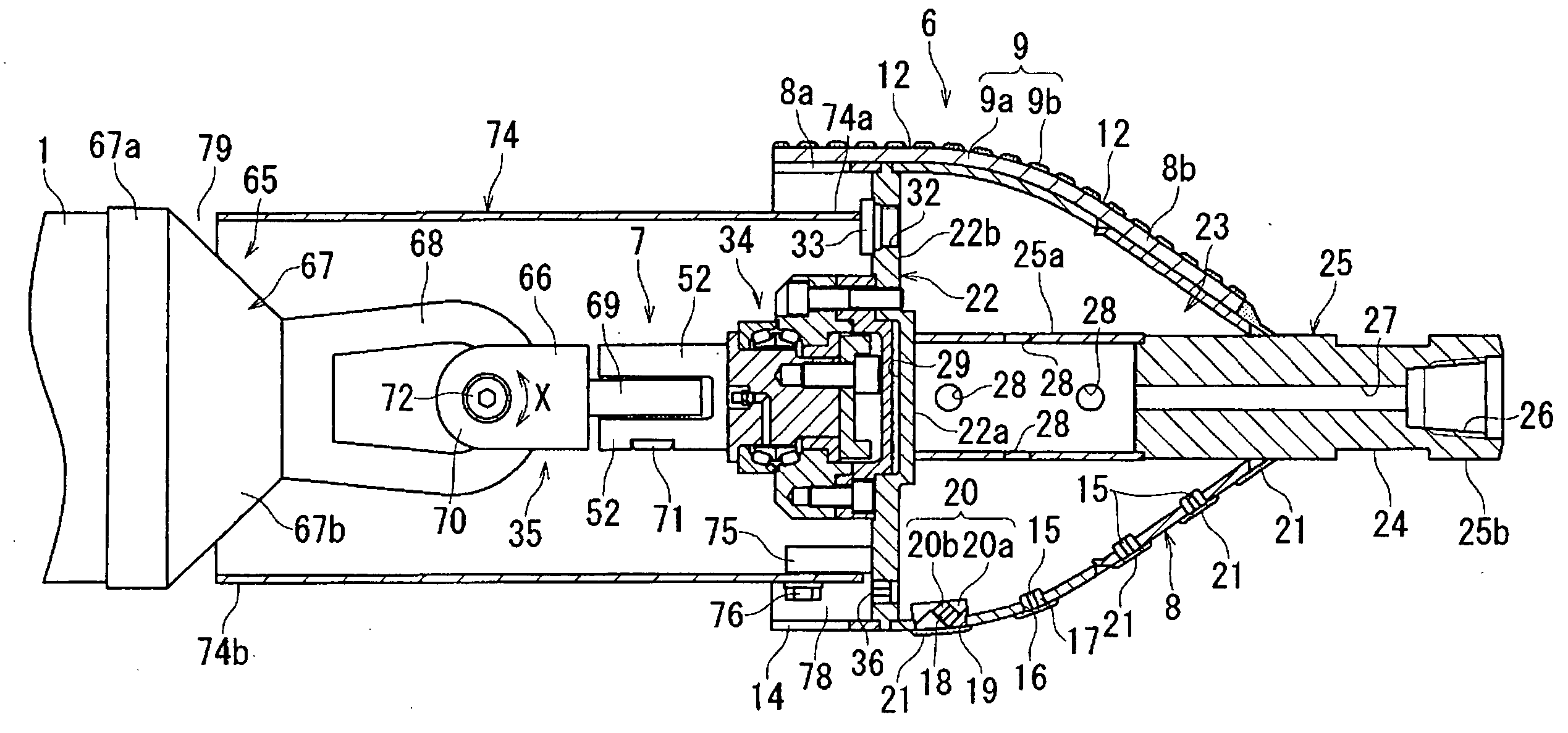
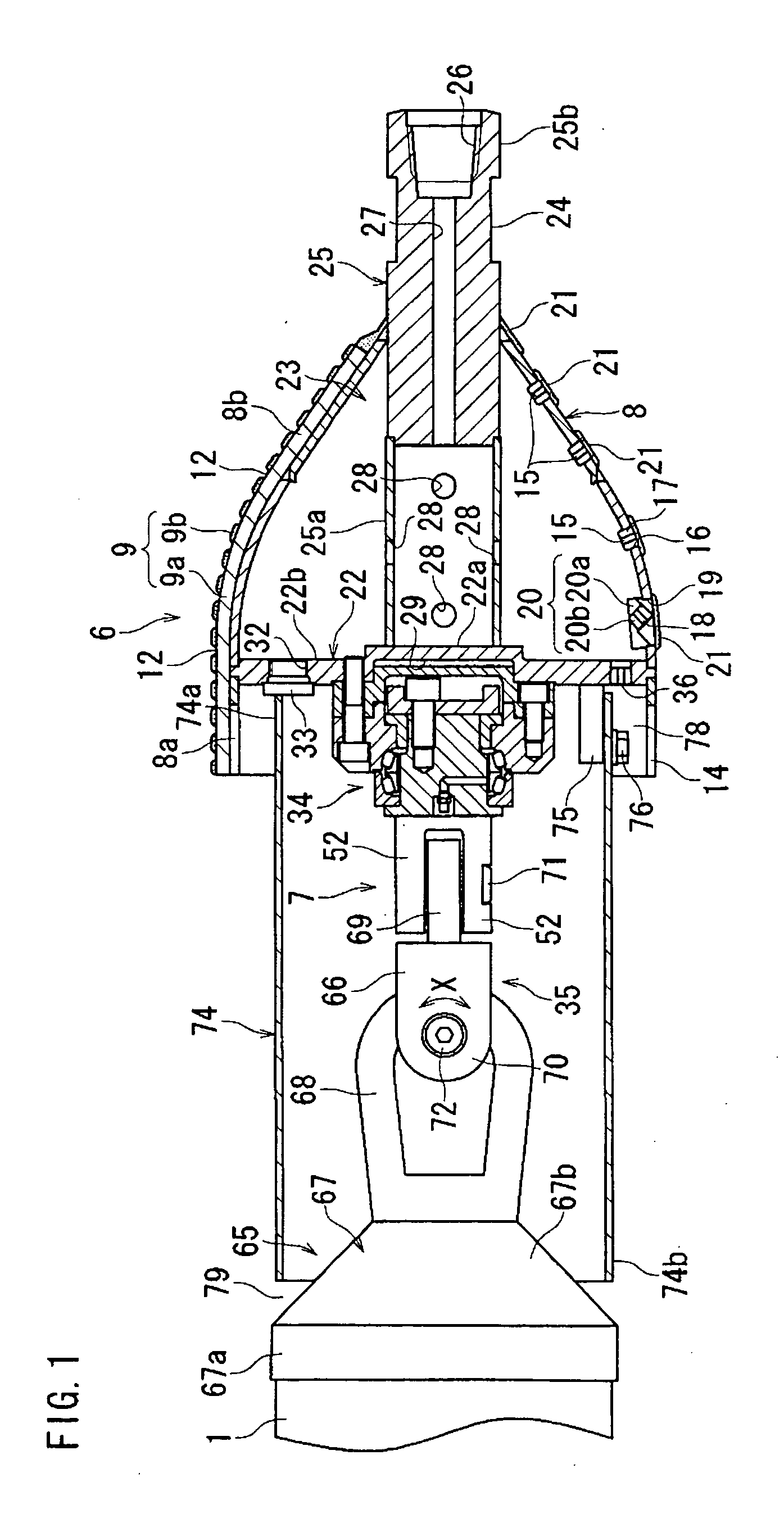
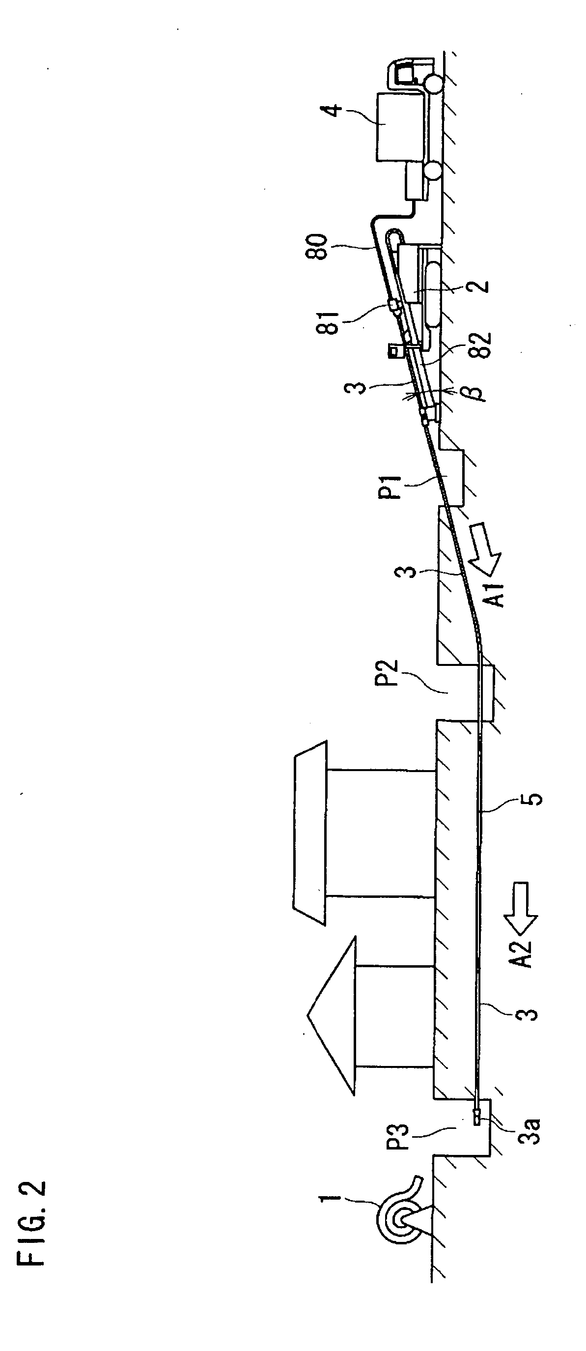
[0036] A concrete embodiment of the reamer apparatus for a ground boring machine of the present invention will now be explained in details while referring to the drawings. FIG. 1 illustrates a sectional view of the reamer apparatus, wherein the reamer apparatus is used for a ground boring machine that is used in the above-described horizontal drilling. The ground boring machine may be comprised by a drill driving device 2 and a drilling fluid feeder 4. While operations of burying a buried pipe 1 by using the ground boring machine are performed through operations as shown in FIGS. 9 and 10, such operations will be briefly explained by using FIGS. 2 and 3. As first shown in FIG. 2, a penetration pit P1, a starting pit P2, and an attainment pit P3 are provided on the ground surface to be separate from each other by specified distances. A rod (hollow rod) 3 mounted with a lead body (pilot head) 3a at its tip end is provided and supported on the drill driving device 2. While drilling flu...
PUM
 Abstract
Description
Claims
Application Information