Reference calibration of metrology instrument

a metrology instrument and calibration technique technology, applied in the field of optical metrology, can solve the problems of degrading the reliability affecting the accuracy of the metrology tool, so as to achieve the effect of easy determination of the calibration error amoun

Inactive Publication Date: 2005-02-17
NANOMETRICS
View PDF3 Cites 55 Cited by
  • Summary
  • Abstract
  • Description
  • Claims
  • Application Information

AI Technical Summary

Benefits of technology

In accordance with an embodiment of the present invention, a metrology instrument is calibrated using two reference locations on one or two separate chips that are designed to produce different measurement results, e.g., different thicknesses. In one embodiment, the metrology device may be an ellipsometer having either a spatially or temporally variable phase retarder. By comparing initial measurements of the two reference locations with later measurements of the two reference locations, the amount of calibration error can be easily determined. In another embodiment, an ellipsometer having a spatially or temporally variable phase retarder is calibrated using a single reference location.

Problems solved by technology

Unfortunately, rotating element configurations require moving parts employing motors, and therefore are more difficult to design into a compact tool.
Furthermore, moving components require maintenance and calibration and may degrade the reliability of the metrology tool.
Unfortunately, photoelastic modulators and Pockels cells are relatively large and expensive.
Consequently, a disadvantage of an ellipsometer configuration employing modulated polarization such as shown in FIG. 2, is the larger size and greater cost relative to an ellipsometer that does not employ modulated polarization.
Calibration of the system, however, requires a periodic reference measurement, which can be time consuming.

Method used


Image

  • Reference calibration of metrology instrument
  • Reference calibration of metrology instrument
  • Reference calibration of metrology instrument

Examples


Embodiment Construction

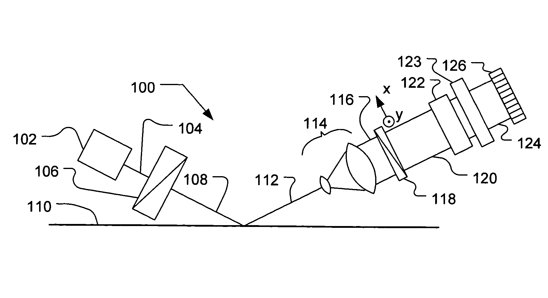
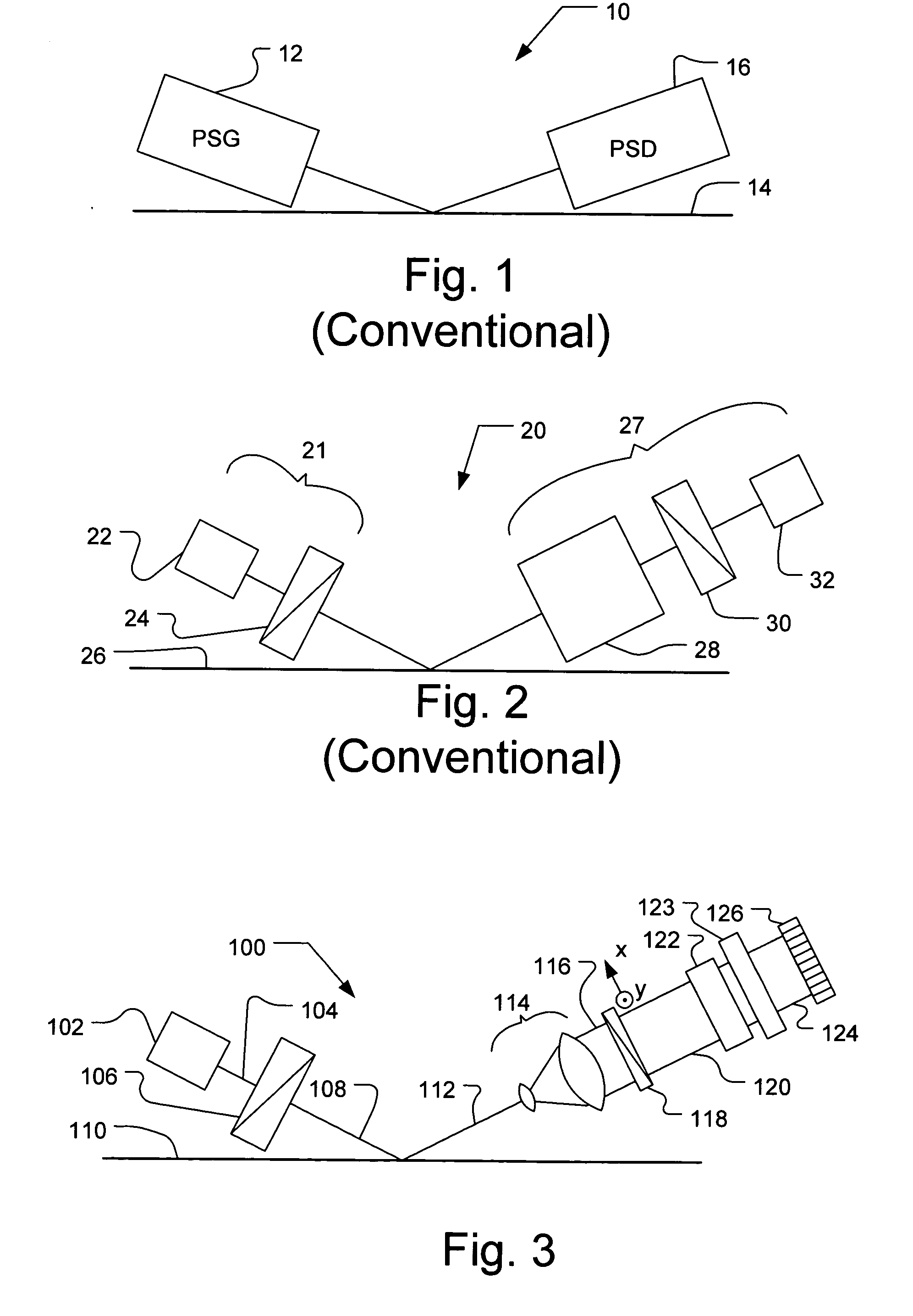
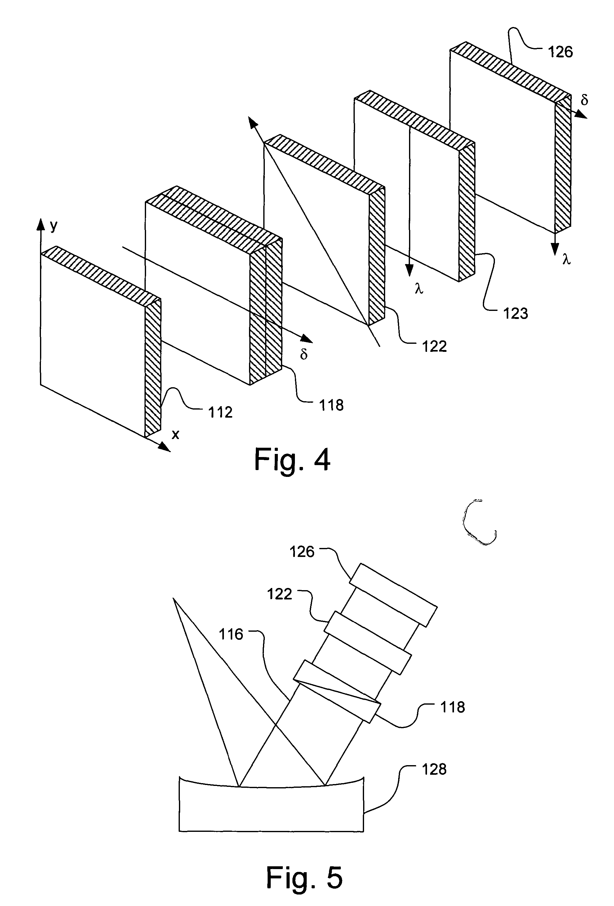
In accordance with an embodiment of the present invention, a metrology device, such as an ellipsometer, has no moving parts and no temporal phase modulator. Such a metrology device is described in U.S. patent application Ser. No. 09 / 929,625, filed Aug. 13, 2001, entitled “Metrology Device and Method Using a Spatial Variable Phase Retarder”, which is incorporated herein by reference. FIG. 3 shows a block diagram of an ellipsometer 100 in accordance with an embodiment of the present invention. After the light beam of known polarization state is reflected from the sample 110, the beam is expanded and passed through a variable retarder 118 to introduce a spatially dependent phase shift. The expanded beam then passes through a polarizer and the intensity is measured using multi-element detector 126. Ellipsometer 100 may be used advantageously for semiconductor thin film applications. Due to its small size, it may be integrated into various semiconductor processor tools.

As shown in FIG...


PUM


Abstract

A metrology instrument is calibrated using two reference locations with different optical properties designed to produce different measurement results, e.g., different thicknesses. The metrology instrument, for example, may be an ellipsometer with a variable phase retarder. By comparing initial measurements of the two reference locations with later measurements of the two reference locations, the amount of calibration error can be easily determined. In addition, an ellipsometer having a spatially or temporally variable phase retarder may also be calibrated with a single reference location.

Description

FIELD OF THE INVENTION The present invention is related to optical metrology and in particular to a calibration technique for a metrology device that uses a spatial and / or temporal phase modulation as a component of an ellipsometer. BACKGROUND There is always a need for precise and reliable metrology to monitor the properties of thin films, especially in the semiconductor and magnetic head industries. Thin film properties of interest include the thickness of one or more layers, the surface roughness, the interface roughness between different layers, the optical properties of the different layers, the compositional properties of the different layers and the compositional uniformity of the film stack. Ellipsometers are particularly well suited to this task when the thickness is less than 100 nm, when there are more than two layers present or when there are compositional variations. Additionally, dimensional measurements such as linewidth, sidewall angle and height can be extracted u...

Claims


Application Information

Patent Timeline
Patent Type & Authority Applications(United States)
IPC IPC(8): G01B11/06G01J4/04
CPCG01J4/04G01B11/0641
Inventor HUANG, CHUNSHENG
Owner NANOMETRICS
Why Eureka
Try Eureka