Reversible fiber optic connector

Active Publication Date: 2005-02-17
PANDUIT
View PDF15 Cites 157 Cited by
  • Summary
  • Abstract
  • Description
  • Claims
  • Application Information

AI Technical Summary

Benefits of technology

[0007] In one embodiment of the invention, there is provided a fiber optic stub fiber connector for reversibly and nondestructively terminating an inserted field fiber having a buffer over a portion thereof. The connector includes a housing and a ferrule including a stub fiber disposed within and extending from a bore extending through the ferrule. The ferrule is at least p

Problems solved by technology

While reversibly rotatable levers have previously been used to effectuate and release an alignment in a fiber optic connector (such as in EP1136860 A2), such connectors have not provided simultaneous buffer clamping and disengagement.
Often such a crimping step may degrade the fib

Method used


Image

  • Reversible fiber optic connector
  • Reversible fiber optic connector
  • Reversible fiber optic connector

Examples


Embodiment Construction

[0046] The invention relates generally to fiber optic connectors and more particularly to pre-polished fiber stub connectors.

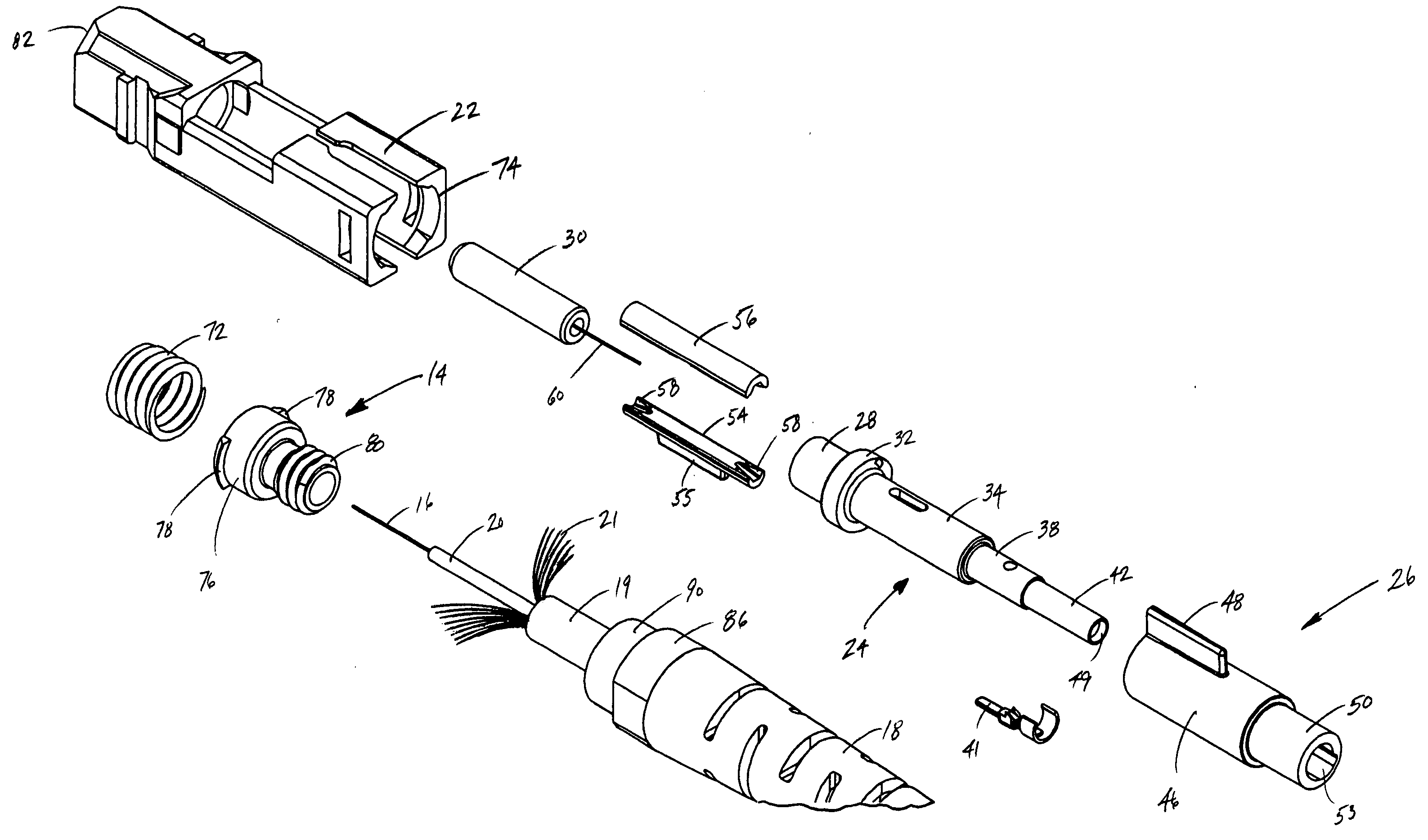
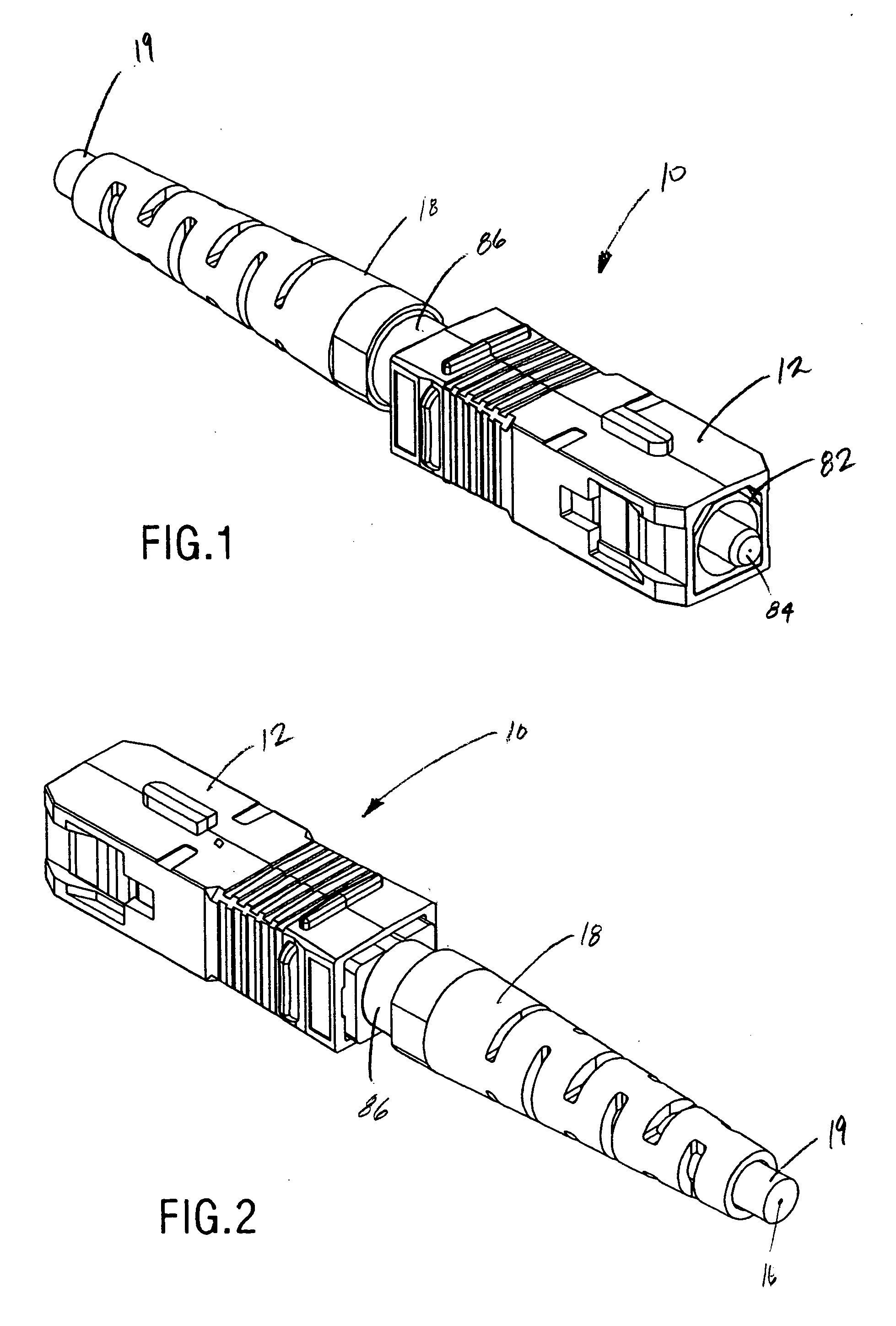
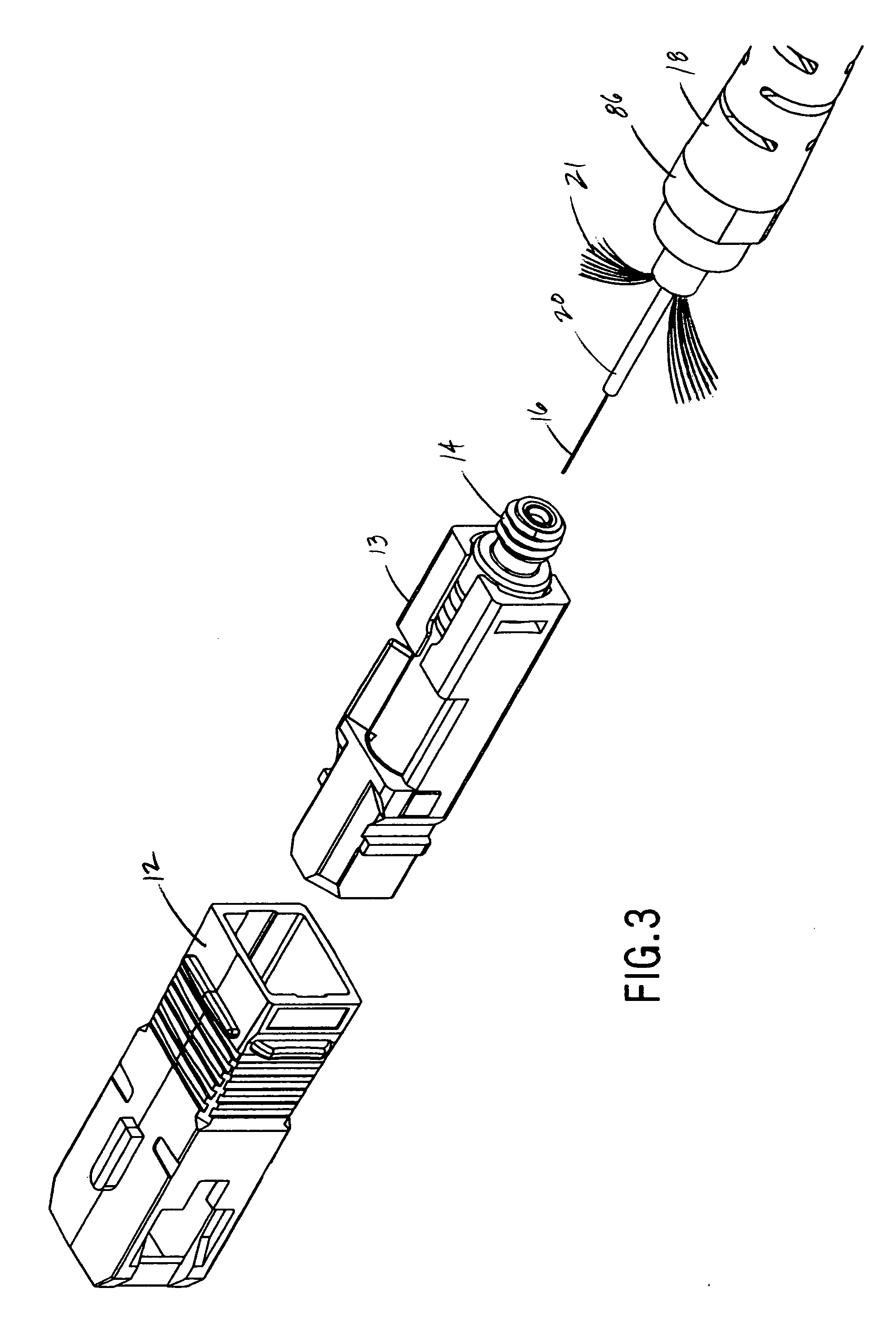
[0047] As seen in perspective in FIGS. 1 and 2 and exploded FIG. 3, a preferred embodiment of a reversible and nondestructive fiber optic stub connector 10 is used to terminate a field fiber. The connector 10 includes an outer housing 12 generally enclosing an SC assembly 13 with a backbone 14. The field fiber 16 is inserted into the connector through the backbone, and a boot / nut assembly having a boot 18 and retention nut 86 overwraps and supports a cable jacket 19 and a buffer 20 surrounding the fiber 16. There may also preferably be Kevlar fibers 21 disposed between the cable jacket and buffer, though in some embodiments the field fiber may only be buffered, with no cable jacket or Kevlar fibers.

[0048] As seen in FIGS. 4 and 5, the SC assembly has an inner housing 22 containing a hollow ferrule holder 24 and a cam sleeve 26. The ferrule holder has a ferru...


PUM


Abstract

A fiber optic stub fiber connector for reversibly and nondestructively terminating an inserted field fiber having a buffer over at least a portion thereof. The connector includes a housing and a ferrule including a stub fiber disposed within and extending from a bore through the ferrule. The ferrule is generally at least partially disposed within and supported by the housing. The connector further includes a reversible actuator for reversibly and nondestructively terminating the inserted field fiber to the stub fiber. The reversible actuator includes a buffer clamp for engaging with the buffer to simultaneously provide reversible and nondestructive strain relief to the terminated field fiber.

Description

BACKGROUND OF THE INVENTION [0001] Fiber optic networks are becoming increasingly commonplace in telecommunications applications due to their increased bandwidth and distance capabilities relative to copper networks. Compared to copper systems, however, fiber optic cables and connections are well-known for their more critical and difficult terminations. For example, the alignment between abutted glass cores within a fiber optic interface is crucial to the performance of the connection. [0002] Field installation of standard “pot and polish” fiber optic connectors is extremely labor- and expertise-intensive. The installer is required to prepare a fiber end, glue the fiber end into the connector, cleave the excess fiber from the endface of the connector, and polish the endface of the connector to obtain the optimum geometry for optical performance. Endface polishing is a difficult and time-consuming step, particularly when using singlemode fiber, and it is best performed by an automate...

Claims


Application Information

Patent Timeline
IPC IPC(8): G02B6/00G02B6/36G02B6/38
CPCG02B6/3806G02B6/3825G02B6/3834G02B6/381G02B6/3858G02B6/3879G02B6/3887G02B6/3846G02B6/3888
Inventor CAVENEY, JACK E.BROUWER, SHAUN P.BARONE, VINCE M.HARTMAN, SCOTT R.STROEDE, ANDREW J.
Owner PANDUIT
Why Eureka
Try Eureka