
Candle system for enhancing burning and improving volatiles performance and a manufacturing method for the same

a technology of volatiles and candle shells, which is applied in the field of candle shell systems, can solve the problems of messy and ugly candle shells, more damage to furniture surfaces, and more damage to furniture surfaces, and achieve the effect of better candle shelling

Inactive Publication Date: 2005-02-17
NAKATSU TETSUO
View PDF16 Cites 66 Cited by
  • Summary
  • Abstract
  • Description
  • Claims
  • Application Information

AI Technical Summary

Benefits of technology

[0012] The primary object of the invention is to provide a system for better candle burning in the container.
[0014] Another object of the invention is to provide better performance of volatiles from the candle with volatiles.
[0015] Another object of the invention is to provide better fragrance performance from the candle.

Problems solved by technology

However, one of the drawbacks of candle is that a part of solid candle wax is liquefied (to melting wax) while it is burning; wherein the m lting wax pool gradually becomes a rather large pool, and the melting wax often times drips from the top of the candle; wherein the candle becomes messy and ugly, and in some case the melting wax can even cause damages such as on furniture surfaces.
Especially, the candle including oils such as fragrance oils possibly causes more damages such as the furniture surface.
Instead of using a container, some people use a plate or a tray to avoid such damage with better burning of the candle because the candle is always exposed to the fresh air (“open-candle”), but dripping of the melting wax almost always takes place; wherein not only the amount of wax is being significantly lost for a long period of time without burning due to wasting dripped wax, but also the dripped melting wax again is solidified and it looks very ugly and makes bad atmospheric mood.
Further as the worst scenario, the spread melting wax on the tray occasionally starts to vigorously burn even without wick and possibly becomes a serious fire hazard.
Further, performance of scented open-candle is poorer than a candle in a container (‘closed-candle’) because the melting wax pool is occasionally broken and the wax drips to give inconsistent fragrance dispersion.
Unfortunately, burning of a closed-candle is generally not very good because of its structural drawback to supply fresh airs (supply oxygens) compared to an open-candle.
However none of these modifications can substantially improve the supply of fresh air to the foot of burning wick and the top surface of candle, which is a significant advantage for open-candles.
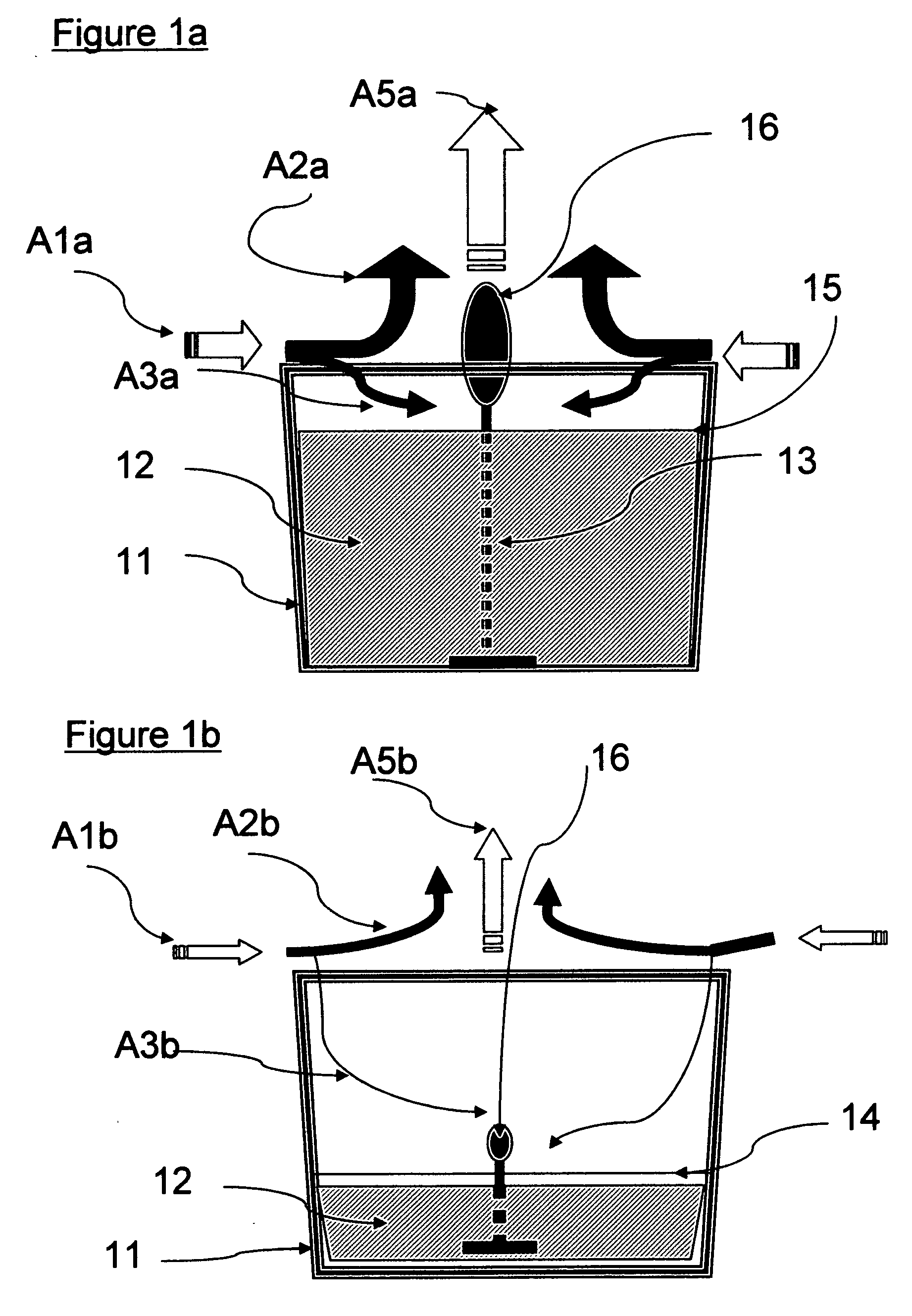
In general, the longer period of time of candle burning, the poorer quality of candle burning because the candle's height and the wick gradually shorten and sinks into the bottom of container and in contrast the wax pool becomes larger and deeper, and as a result the supply of the fresh air to the foot of the burning wick and top surface of candle becomes gradually less and less.
Specifically, as if it is contradictive, the better burning, the poorer the fresh air to the foot of the burning wick.
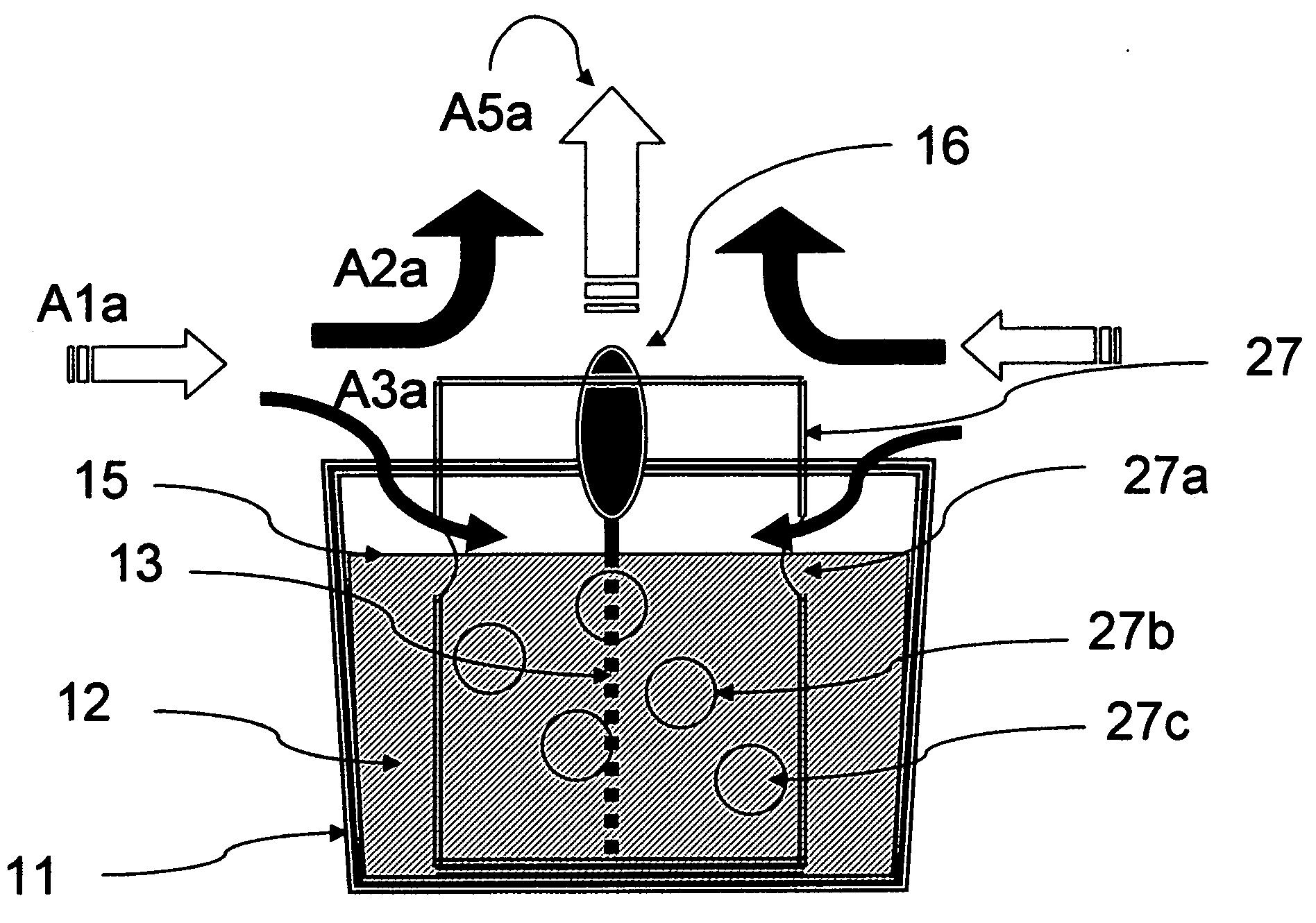
Accordingly to these air flows the candle flame 16 becomes smaller which means poor burning, and poor volatility of the volatiles from the wax pool 14 resulting in poor volatiles' performance.
As a result of the multiple disadvantages inherent with conventional delivery candle systems, manufacturers have been forced to respond by (1) changing the wax base material to a more expensive substance, (2) changing the wick material to a more expensive one having a lower temperature of combustion, (3) improving the thermal resistance of the active volatiles placed in the base material, (4) increasing the concentration of volatile components within the base material to an expensive and unnecessarily high concentration, and (5) placing hoods above the wick in attempts to minimize wick flare-ups and re-radiate heat downward to minimize irregular molten pool shapes.
Unfortunately, available commercial candle-base systems are only positioned to protect the candle flame from being blown out or for pleasing decoration or design purposes.
Many candle hoods substantially decrease volatile performance because of inadequate design and use.
There is not such a simple and feasible system to be able to supply the fresh air to the lower inside part of the candle container.
Consequently, volatiles that escape from the molten pool are forced into a narrow cone containing the hot combustion gasses, and are thermally consumed.
Volatiles that do escape the hot combustion gasses experience the additional turbulence resulting from the pressure gradient between the wide bottom and narrow top openings of the hood.
In addition, the disclosed invention does not improve any air supply to the inside of candle container.
The Lee system further minimizes performance volatile distribution by trapping the volatiles and combustion gasses below a bowl (and cup) thus creating a positive downward pressure and increased turbulence to further minimize volatile distribution.

Method used


Image

  • Candle system for enhancing burning and improving volatiles performance and a manufacturing method for the same
  • Candle system for enhancing burning and improving volatiles performance and a manufacturing method for the same
  • Candle system for enhancing burning and improving volatiles performance and a manufacturing method for the same

Examples


embodiment 1

[0033]

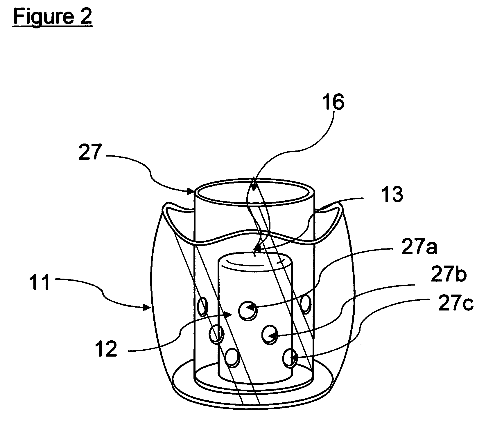
[0034] The present invention is manufactured by the following method, but not limited. For example, the 12 holes with 8 mm diameter are made by using the electric drill on the sidewall of the plastic inner-tube 57 mm diameter×70 mm height. The four holes are placed at the upper portion of the inner-tube every 90 degree at ca. 20 mm lower from the top edge, another 4 holes are placed at the lower portion of the inner-tube every 90 degree and 30 degree turned from the upper holes at ca. 32 mm lower from the top edge, and more 4 holes are drilled at the lowest portion of the inner-tube every 90 degree and 60 degree turned from the upper holes at ca. 52 mm lower from the top edge. The above inner-tube can be applied with an appropriate size container, for example, 75 mm diameter×70 mm height glass jar, for an appropriate pillar-type candle, for example, 50 mm diameter×50 mm height to be sit in the inside of the inner-tube.

embodiment 2

[0035]

[0036] The present invention is manufactured as described in Embodiment 1 and then the aforementioned inner-tube is sit in the inside container, for example, 75 mm diameter×70 mm height glass jar, and an appropriate length of wick is set in the inside of the inner-tube followed by filling with an appropriate volume of melting candle wax either with or without volatiles, and being solidified for use.

embodiment 3

[0037]

[0038] Th container of the pres nt invention is compared with traditional candle container. Two commercial scented candles in the container (closed-candle) were purchased from a local supermarket. Both candle waxes and wicks are removed from the containers and are melted. The inner-tube is set to the bottom of one of the containers and the melting wax are poured into both containers with the same formula of commercial candle. After two hours, both candles' performances are compared.

Test CandleControl CandleTime(with a inner-tube having holes)(no inner-tube)0Very good burning with brighterVery good burning withflamebright flame2 hoursVery good burning and strongPoor burning with poorupdraft with very good fragrancefragrance performanceperformance


PUM

PropertyMeasurementUnit
diameter×70aaaaaaaaaa
diameter×50aaaaaaaaaa

Abstract

A system and a method for enhancing burning candle and improving volatiles performance with a tube having holes and / or cuts or a candle container having at least one inner-tube having holes and / or cuts, continuously supplying the fresh air through the holes and / or cuts, and supplying the fresh air to the foot of the burning wick, and for manufacturing the same.

Description

BACKGROUND OF THE INVENTION [0001] This invention relates generally to the field of candle system and more specifically to a system and a method for enhancing candle burning and improving volatiles' performance and further relates to a method for manufacturing the same. This invention further specifically relates to a system and a method to continuously supply the fresh air to near the foot of the burning wick and the top surface of candle in a candle container. [0002] Candles have traditionally been used to lighten the dark and are still an important light source in some countries and still an important emergency light source even in the developed countries when the electric light source is shut off for any reason. In addition, candles are used to heat up some materials such as portable foods. Nowadays candles with volatiles are very common in providing fragrance, aromas, pesticides, and even anti-microbial compounds into the atmosphere for a wide variety of reasons. In addition to...

Claims


Application Information

Patent Timeline
Patent Type & Authority Applications(United States)
IPC IPC(8): C11C5/00F23D3/16F23D3/22
CPCC11C5/008F23D3/22F23D3/16
Inventor NAKATSU, TETSUO
Owner NAKATSU TETSUO
Learn More