Communication apparatus
a communication apparatus and multi-carrier technology, applied in the field of communication apparatus and multi-carrier transmission system, can solve the problems of transmission path estimation, which is carried out in the receiving device, cannot follow sufficiently to instantaneous fluctuation and periodical fluctuation of wide, and achieve the effect of enhancing transmission efficiency
- Summary
- Abstract
- Description
- Claims
- Application Information
AI Technical Summary
Benefits of technology
Problems solved by technology
Method used
Image

Examples
embodiment 1
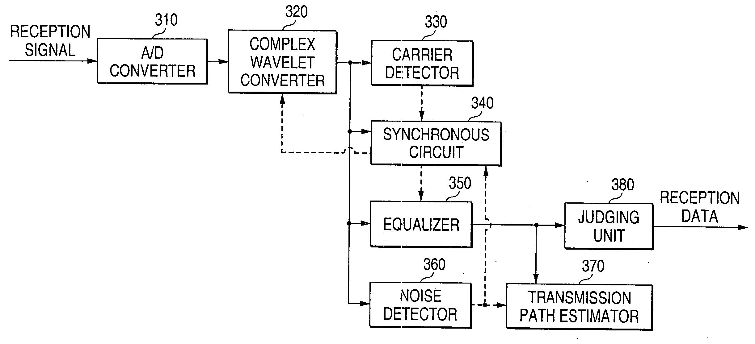
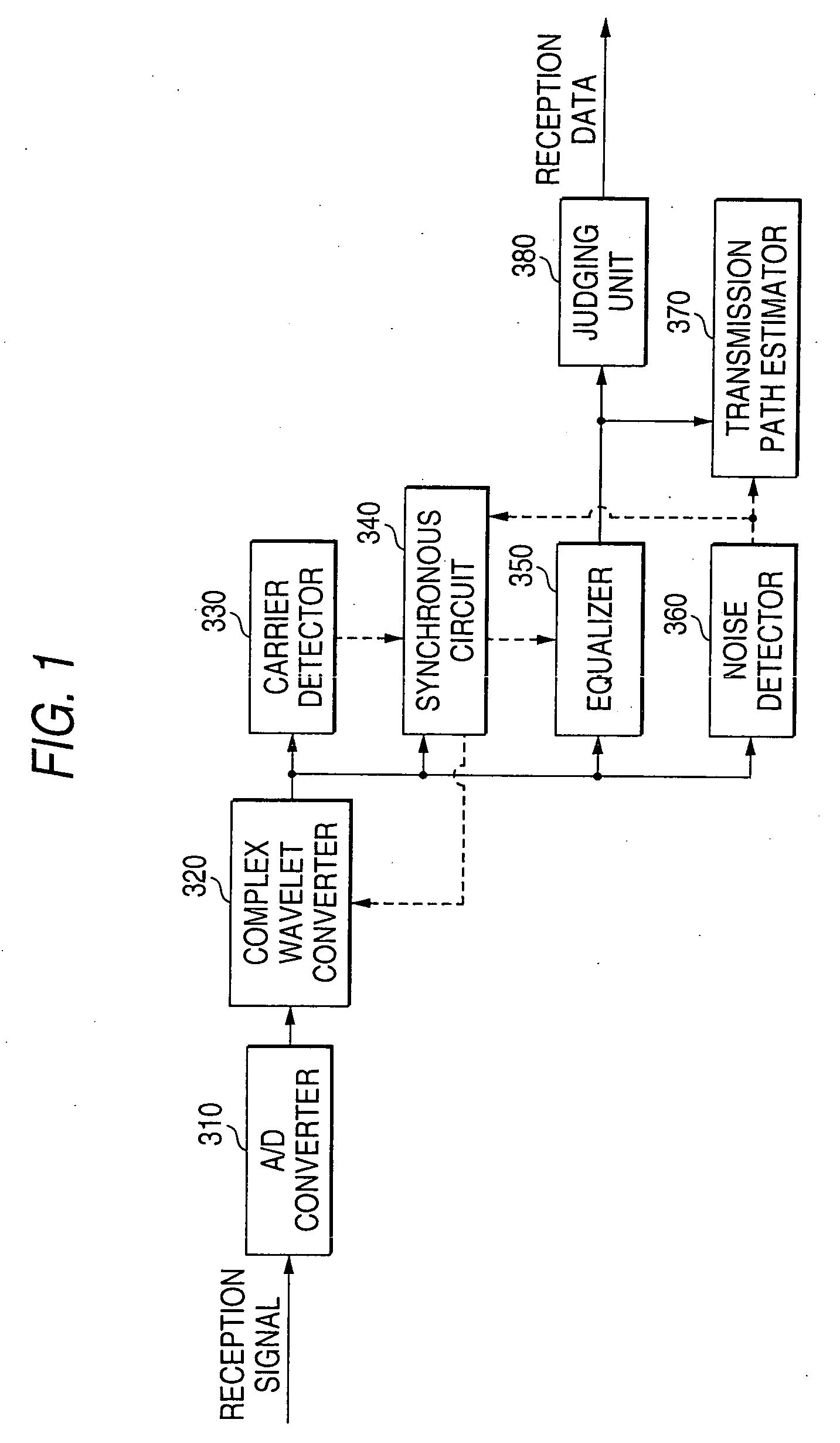
[0035]FIG. 1 is a block diagram which shows a receiving device in this invention. In passing, a transmitting device is the same as the transmitting device 299 of FIG. 19, as to which an explanation was carried out in the conventional technology.
[0036] In FIG. 1, 310 designates an A / D converter which converts an analog signal into a digital signal, and 320 designates a complex wavelet converter which generates a in-phase signal and an orthogonal signal by wavelet-converting a reception signal, and 330 designates a carrier detector for detecting a transmission signal which is transmitted from a transmitting device, and 340 designates a synchronous circuit for synchronizing with the reception signal, and 350 designates an equalizer for compensating a signal which was distorted by influence of a transmission path, and 360 designates a noise detector which detects presence or absence of narrow-band noise in each sub carrier band, by use of a signal after complex wavelet conversion, and 3...
embodiment 2
[0050] (Embodiment 2)
[0051]FIG. 4 is a block diagram which shows a receiving device in an embodiment 2 of this invention. In passing, a transmitting device is the same as the transmitting device 299 of FIG. 19.
[0052] In addition, a difference between the receiving devices of FIG. 4 and of FIG. 1 is only an AGC (Automatic Gain Control) circuit 390. Since other circuits are the same as the circuits which were explained in FIG. 1, descriptions are pursuant to the descriptions in the embodiment 1. 390 designates an AGC circuit which automatically adjust a gain of a reception signal. Next, by use of FIG. 4 and FIG. 5, an operation in case that this system was applied to the power line communication will be described. FIG. 5 is a view which shows a noise characteristic in case that wide-band noise was added in a power line transmission path.
[0053] A difference from the embodiment 1 is to carry out noise detection by the noise detector 360 including a gain which is used by the AGC circui...
embodiment 3
[0059] (Embodiment 3)
[0060] A transmission path estimator in an embodiment 3 of this invention will be described. In this embodiment, a receiving device, and a transmitting device of a communication apparatus are the same as in the embodiment 1 or 2.
[0061]FIG. 7 shows a frame configuration view in case of carrying out transmission path estimation by use of time of a power supply cycle.
[0062] Next, an operation will be described. FIG. 6 shows a frame configuration view for explaining an operation of a normal transmission path estimator.
[0063] Normally, as shown in FIG. 6, a transmission path estimation frame is added in a frame to be transmitted and received (in the figure, a “CE frame” is the “transmission path estimation frame”).
[0064] Generally speaking, in a transmission path estimating method of the suchlike configuration, this transmission path estimation frame is used again on an irregular basis, when a transmission path fluctuates significantly, and if a past transmission...
PUM
 Abstract
Description
Claims
Application Information
PatSnap Eureka turns technology decisions into work you can execute. Powered by our Innovation Knowledge Graph, it runs expert workflows across engineering, life sciences, materials and intellectual property. Get your review-ready output in minutes.


