Flow sensor with integrated delta P flow restrictor

a flow restrictor and flow sensor technology, applied in the field of high mass flow sensors, can solve the problems of no longer corresponding to the accurate flow rate value of the measured resistance of an anemometer or other sensor, and not holding at high flow velocity, so as to achieve the effect of minimizing turbulen

Inactive Publication Date: 2005-02-24
RESPIRONICS
View PDF12 Cites 61 Cited by
  • Summary
  • Abstract
  • Description
  • Claims
  • Application Information

AI Technical Summary

Benefits of technology

[0012] The restrictor of this invention includes a body portion having a generally cylindrical shape with an upstream end and a downstream end separated by a center portion. Pressure taps are located proximate the junction of the ends with the center portion, whereby flow passes from upstream to downstream in parallel through the sensor, which is conventional, and the restrictor of the present invention. The upstream end has a decreasing tapering inner surface for contact with the flow of fluid through the restrictor. Similarly, the downstream end has an increasing tapering inner surface for contact with the flow as it leaves the restrictor. The center portion has radial and axial restrictor elements positioned in the path of flow through the center portion. The restrictor elements have tapered leading edges to minimize turbulence.

Problems solved by technology

There are numerous drawbacks to these and other known flow sensors.
One drawback is that the proportional relationship upon which these sensors operate, i.e., that the conductive wire or element will cool linearly with increases in the flow rate of the fluid due to forced convection, does not hold at high flow velocities where the sensors become saturated.
As a result, in high flow regions, measured resistance of an anemometer, or other sensor, no longer correlates to an accurate value of the flow rate.
Furthermore, because these sensors reside in the main flow channel, they are susceptible to physical damage and contamination.
Though they offer some improvement over sensors disposed directly in the flow channel, all of these indirect flow sensors are hampered by calibration problems.
An indirect flow sensor may be calibrated to work generally with certain types of restrictors, e.g., honeycomb restrictors, but imprecise restrictor geometry results in variations in pressure and, therefore, variations in measured flow rate.
Furthermore, the sensors are not calibrated for use with other types of restrictors.

Method used


Image

  • Flow sensor with integrated delta P flow restrictor
  • Flow sensor with integrated delta P flow restrictor
  • Flow sensor with integrated delta P flow restrictor

Examples


Embodiment Construction

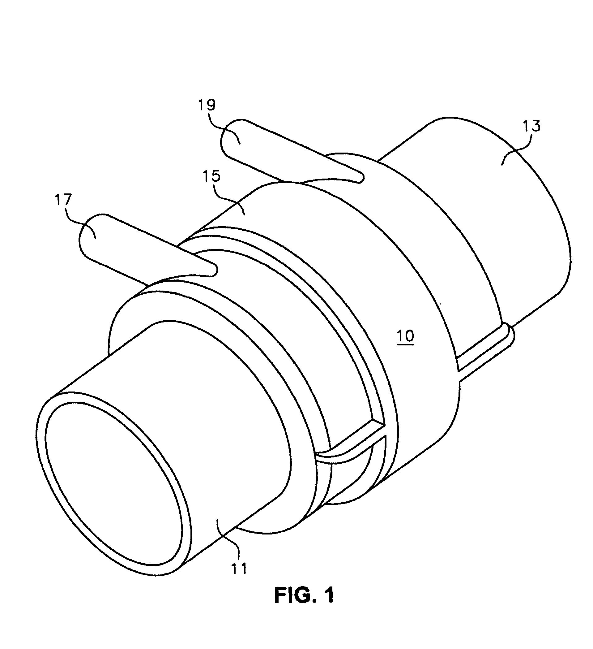
[0019] The present invention provides for substantial improvements in the operation of a fluid flow sensor, 10 generally, such as that shown in FIG. 1. The sensor is fitted in a flow path such that fluid, either liquid or gas as the system dictates, enters the inlet 11 and exits outlet 13. The body 15 of the sensor includes pressure tap inlet 17 and outlet 19 where fluid is removed and measured using conventional equipment, not shown.

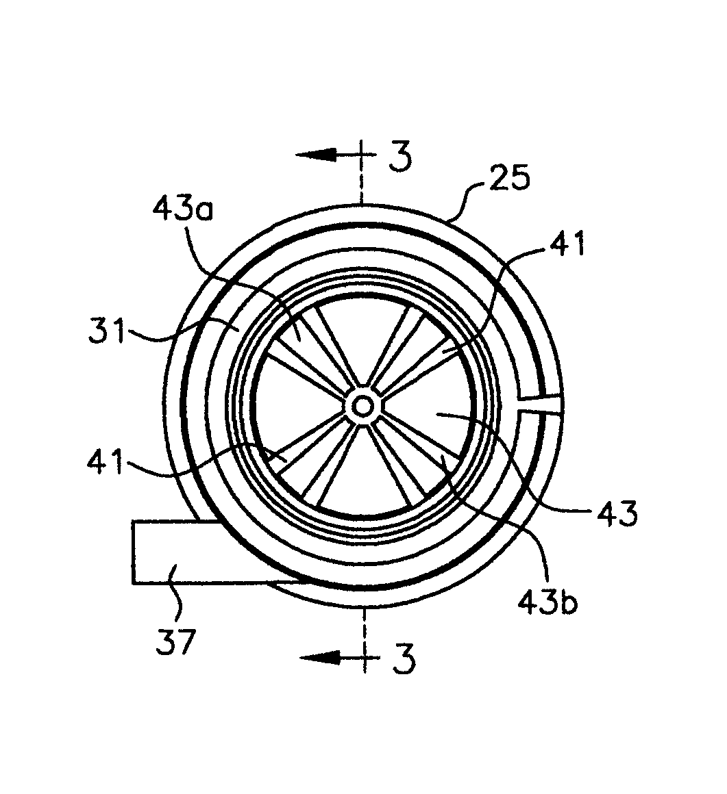
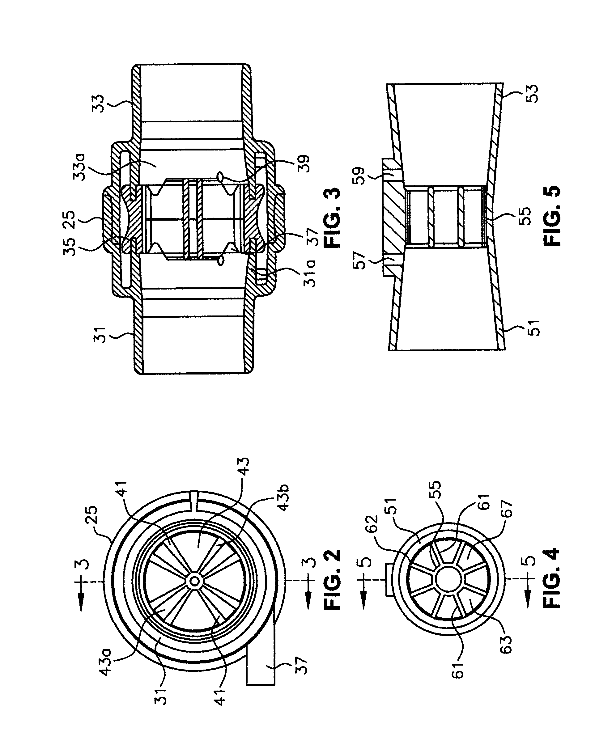
[0020] Body 15 contains a flow restrictor that is provided to handle the fluid flow as it passes through the body and fluid is directed to the airflow or pressure sensor via inlet 17 and outlet 19. FIGS. 2 and 3 represents a prior art flow sensor and flow restrictor, where body 25 includes a cylindrical inlet portion 31, a cylindrical outlet portion 33 and a flow restrictor 35 in the middle. Pressure taps 37 and 39 feed the inlet and outlet 17 and 19 respectively of FIG. 1. A plurality of vanes 41 define a plurality of channels 43 though which fluid fl...


PUM


Abstract

A high mass flow sensor device having a flow restrictor formed by a body having a generally cylindrical shape with an upstream end and a downstream end separated by a center portion having pressure taps proximate the junction of the ends with the center portion. Flow passes from upstream to downstream. The upstream end has a decreasing tapering inner surface for contact with the flow and the downstream end having an increasing tapering inner surface for contact with the flow. A center portion has radial and axial restrictor elements positioned forming axial openings in the path of flow through the center portion. The restrictor elements having tapered leading edges. One opening is formed by a central tube having a predetermined diameter and the remaining openings are radially extending members supporting the central tube, each of the radially extending members having substantially the same cross-sectional area as the central tube.

Description

FIELD OF THE INVENTION [0001] The present invention relates to a high mass flow sensor having a restrictor and an airflow sensor in parallel with the restrictor. More particularly, the invention relates to an improved design of the restrictor itself. BACKGROUND OF THE INVENTION [0002] Flow rate control mechanisms are used in a variety of flow systems as a means for controlling the amount of fluid, gaseous or liquid, traveling through the system. In large-scale processing systems, for example, flow control may be used to affect chemical reactions by ensuring that proper feed stocks, such as catalysts and reacting agents, enter a processing unit at a desired rate of flow. Additionally, flow control mechanisms may be used to regulate flow rates in systems such as ventilators and respirators where, for example, it may be desirable to maintain a sufficient flow of breathable air or provide sufficient anesthetizing gas to a patient in preparation for surgery. [0003] Typically, flow rate c...

Claims


Application Information

Patent Timeline
Patent Type & Authority Applications(United States)
IPC IPC(8): A61M16/00G01F1/40G01F1/42G01F1/44
CPCA61M2016/0036G01F1/44G01F1/42G01F1/40
Inventor SPELDRICH, JAMIE W.
Owner RESPIRONICS
Why Eureka
Try Eureka