Unidirectional, multi-head fiber placement

a fiber placement and multi-head technology, applied in the direction of paper hanging, other domestic objects, chemistry apparatus and processes, etc., can solve the problems of inability to control the outside surface of the part, such as the fuselage section, and the prior art process of fiber placement and tape laying is currently too slow to be economically viable to meet the production rate of new large-scale aircraft programs

Active Publication Date: 2005-02-24
THE BOEING CO
View PDF6 Cites 63 Cited by
  • Summary
  • Abstract
  • Description
  • Claims
  • Application Information

AI Technical Summary

Problems solved by technology

One problem with this approach is that controlling the outside surface of the part—such as a fuselage section—is not possible without transferring the part to a female tool or clam shell type tooling.
Prior art processes such as tape laying and fiber placement are currently too slow to be economically viable to meet production rates on new large scale aircraft programs, such as Boeing's 7E7.

Method used


Image

  • Unidirectional, multi-head fiber placement
  • Unidirectional, multi-head fiber placement
  • Unidirectional, multi-head fiber placement

Examples


Embodiment Construction

[0021] The following detailed description is of the best currently contemplated modes of carrying out the invention. The description is not to be taken in a limiting sense, but is made merely for the purpose of illustrating the general principles of the invention, since the scope of the invention is best defined by the appended claims.

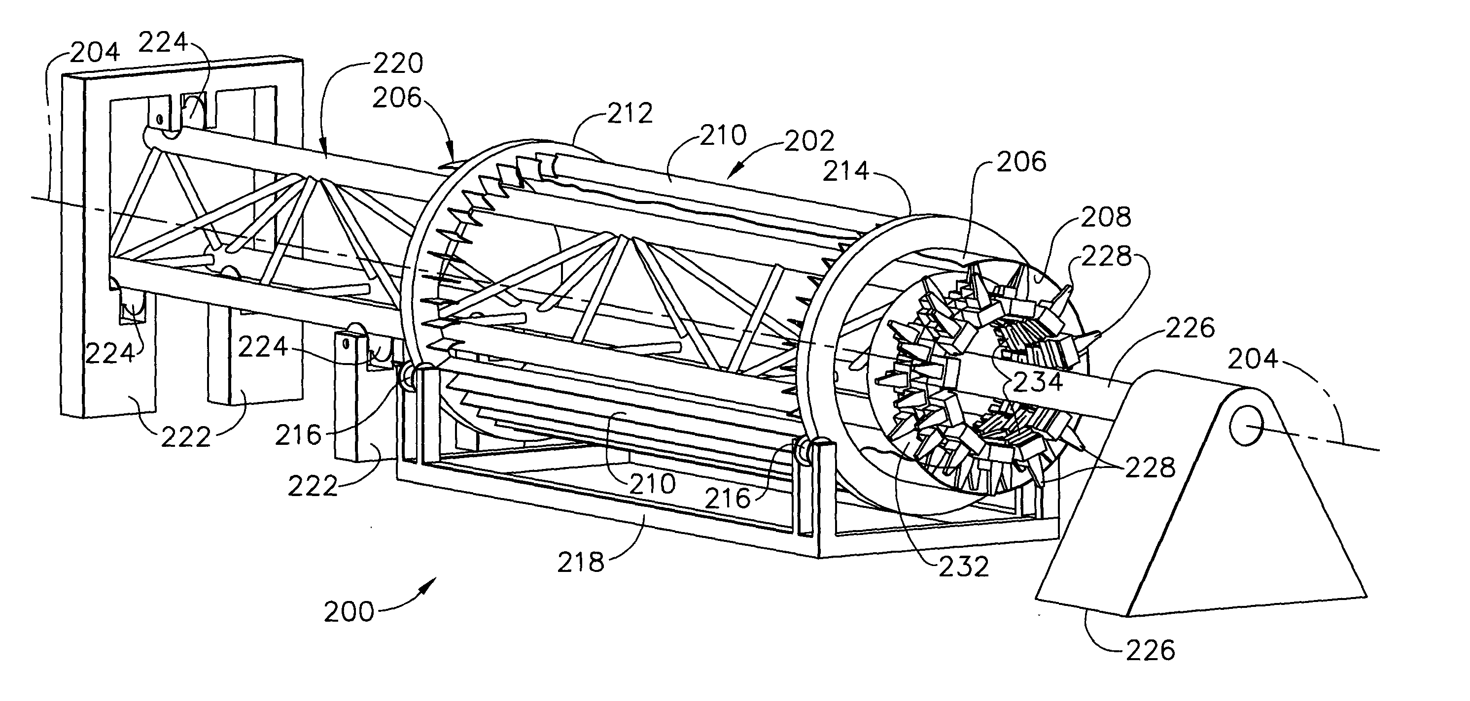
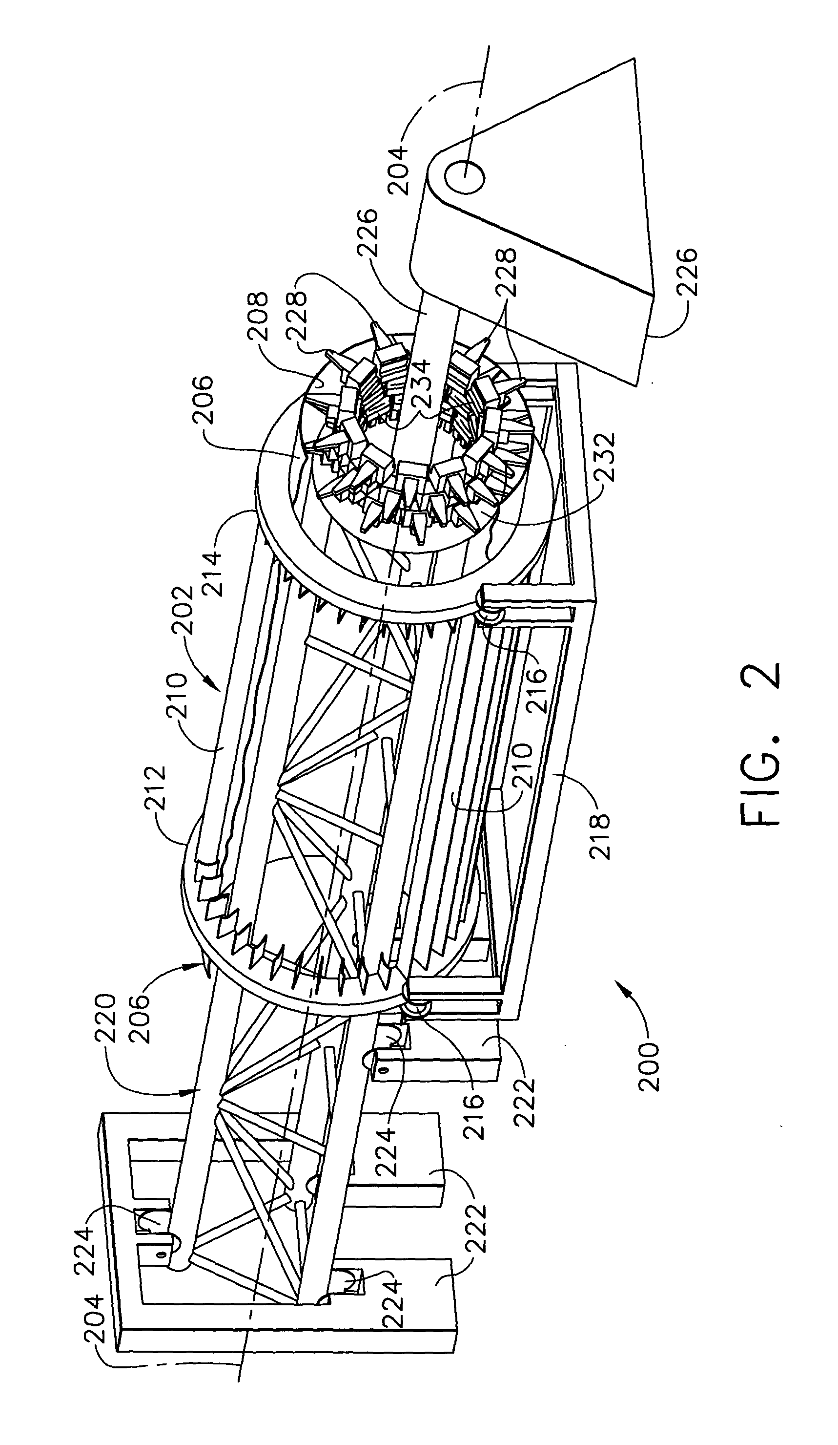
[0022] Broadly, one embodiment of the present invention provides fabrication of parts made of composite materials, which may be used, for example, in the manufacture of commercial and military aircraft. In one embodiment, an automated lay-up machine allows material placement directly to an outside mold surface and eliminates prior art techniques of expansion and transfer of the part to another tool, allowing greater control and accuracy over the prior art in forming the exterior surface of the part and resulting in less defects and higher surface quality compared to parts fabricated according to the prior art. In one embodiment, the present invention ...


PUM

PropertyMeasurementUnit
diameteraaaaaaaaaa
widthsaaaaaaaaaa
widthsaaaaaaaaaa

Abstract

An aircraft part manufacturing device for automated composite lay up includes a mandrel tool having a an interior mandrel surface that conforms to an outside mold line (OML) of a part: to be manufactured. One or more circular rings surround the mandrel and are attached to the mandrel. The circular rings rotate supported by bearings in a bearing cradle so that the mandrel rotates concentrically with the circular rings about an axis of rotation passing through the center of the circular rings. Multiple composite material delivery heads simultaneously deliver material directly to the outside mold line on the interior mandrel surface while the mandrel is rotated. A cantilever supported gantry beam supports the material delivery heads inside the interior mandrel surface. A connecting mechanism connects the material delivery heads to the gantry beam and provides motion of the material delivery heads relative to the interior mandrel surface.

Description

BACKGROUND OF THE INVENTION [0001] The present invention generally relates to fabrication of large composite structures and, more particularly, to automated composite lay-up of large aircraft fuselage sections. [0002] The structural performance advantages of composites, such as carbon fiber epoxy and graphite bismaleimide (BMI) materials, are widely known in the aerospace industry. Aircraft designers have been attracted to composites because of their superior stiffness, strength, and radar absorbing capabilities, for example. As more advanced materials and a wider variety of material forms have become available, aerospace usage of composites has increased. Automated tape layer technology has developed to become a widely used automated process for fabrication of large composite structures such as wing panels and empennage. Current tape layer technology has been improved to offer flexibility in process capabilities required for a wide variety of aerospace components. As aerospace indu...

Claims


Application Information

Patent Timeline
Patent Type & Authority Applications(United States)
IPC IPC(8): B29C53/72B29C53/80B29C70/32B29C70/38
CPCB29C53/72B29C53/8016B29C70/32B29C70/326Y10T156/1348B29L2031/3082Y10T156/1795Y10T156/1788B29C70/386
Inventor CLARK, RANDALL R.ENGWALL, DWIGHT L.YONASH, MARK G.NEW, JEFFREY A.
Owner THE BOEING CO
Why Eureka
Try Eureka