Gas sensor

Inactive Publication Date: 2005-02-24
ROBERT BOSCH GMBH
View PDF6 Cites 5 Cited by
  • Summary
  • Abstract
  • Description
  • Claims
  • Application Information

AI Technical Summary

Benefits of technology

[0005] The gas sensor according to the present invention has the advantage that it increases the internal resistance by the arrangement of the reference-gas region inside the electrochemical cell, that is to say, between the first and second electrode. Furthermore, the characteristic curve of the int

Problems solved by technology

Furthermore, the temperature dependency of the internal resistance is low compared to the

Method used


Image

  • Gas sensor
  • Gas sensor

Examples


Embodiment Construction

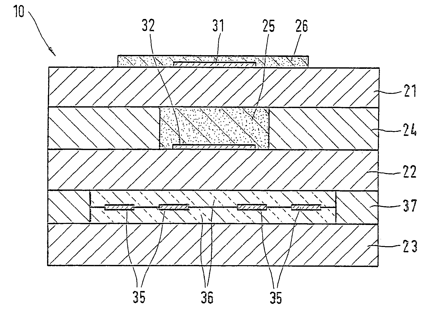
[0013]FIG. 1 schematically shows as an exemplary embodiment of the present invention a planar sensor element 10 having a layer-type structure and a first, a second and a third solid electrolyte member 21, 22, 23 made of an ion-conducting material. A first electrode 31, which is exposed to a measuring gas, is arranged on first solid electrolyte member 21, on the outer surface of sensor element 10. First electrode 31 is covered by a porous protective layer 26. Arranged on the side of first solid electrolyte member 21 lying across from first electrode 31, between first and second solid electrolyte member 21, 22, is a reference-gas region 25, which is filled with an electrically insulating, porous material, such as porous aluminum oxide. Reference-gas region 25 contains a reference gas, such as atmospheric air, extends along the longitudinal axis of sensor element 10 and is in contact with the atmospheric air by the end of sensor element 10 (not shown) that is exposed to the atmospheric...


PUM


Abstract

A gas-measuring sensor, preferably for verifying at least one physical variable of a gas, in particular for verifying the oxygen concentration in an exhaust gas of an internal combustion engine, the sensor including a sensor element, which has an electrochemical cell having a first electrode and a second electrode and at least one solid electrolyte electrically connecting the first and the second electrode. The second electrode is provided in a reference-gas region containing a reference gas. The reference-gas region is arranged between the first and the second electrode.

Description

BACKGROUND INFORMATION [0001] A gas-measuring sensor is described in German Patent No. 100 58 643, for instance. The gas-measuring sensor has a sensor element including a first, a second and a third solid electrolyte member arranged in the form of layers. Applied on the first solid electrolyte member, on an outer surface of the sensor element, is a first electrode. A second electrode is provided on the side of the first solid electrolyte member lying across from the first electrode. The second electrode is arranged in a reference-gas region between the first and the second solid electrolyte member. The first and the second electrode as well as the solid state electrolyte arranged between the electrodes form an electrochemical cell, such as a Nernst cell. The reference-gas region, which may be filled with a porous material, contains a reference gas, such as air. A heater for heating the sensor element is provided between the second and the third solid electrolyte member, the heater b...

Claims


Application Information

Patent Timeline
IPC IPC(8): G01N27/407G01N27/409G01N27/41
CPCG01N27/4071
Inventor WAHL, THOMASHANDLER, TORSTEN
Owner ROBERT BOSCH GMBH
Why Eureka
Try Eureka