All-solid battery and manufacturing method therefor
- Summary
- Abstract
- Description
- Claims
- Application Information
AI Technical Summary
Benefits of technology
Problems solved by technology
Method used
Image

Examples
examples
[0066]Examples 1 to 13 of all-solid batteries prepared in accordance with the manufacturing method according to the present invention and a comparative example will be described below.
[0067]First, in order to prepare all-solid batteries according to Examples 1 to 12 and the comparative example, the following materials were prepared as starting raw materials for the solid electrolyte layer, positive electrode layer, negative electrode layer, and current collector layer.
[0068]Prepared were a glass powder with a composition of Li1.5Al0.5Ge1.5(PO4)3 as a solid electrolyte material, a powder including a crystalline phase of NASICON-type structure with a composition of Li3V2(PO4)3 as a positive electrode active material, a titanium dioxide powder of anatase-type crystal structure as a negative electrode active material, a carbon powder as an electron-conducting material, and a glass ceramic powder with a composition of Li1.0Ge2.0(PO4)3 as a sintering material.
[0069]The materials mentioned...
examples 1 to 5
Comparative Example
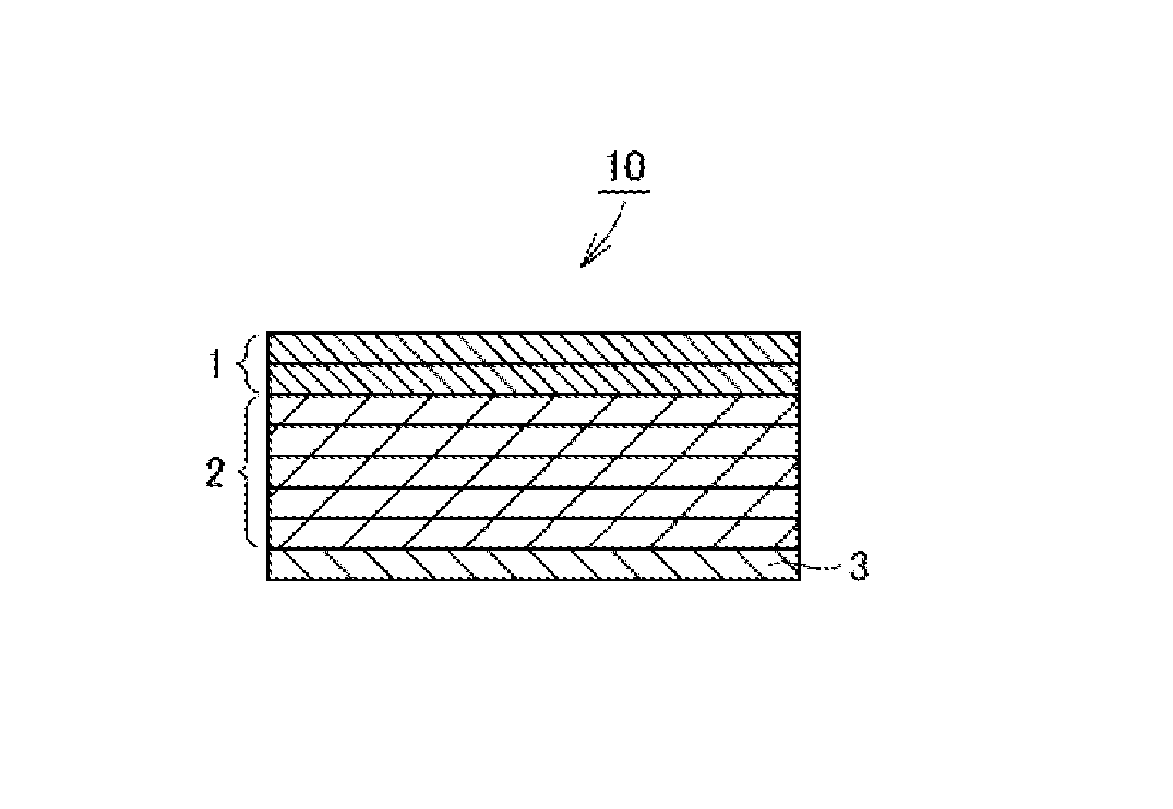
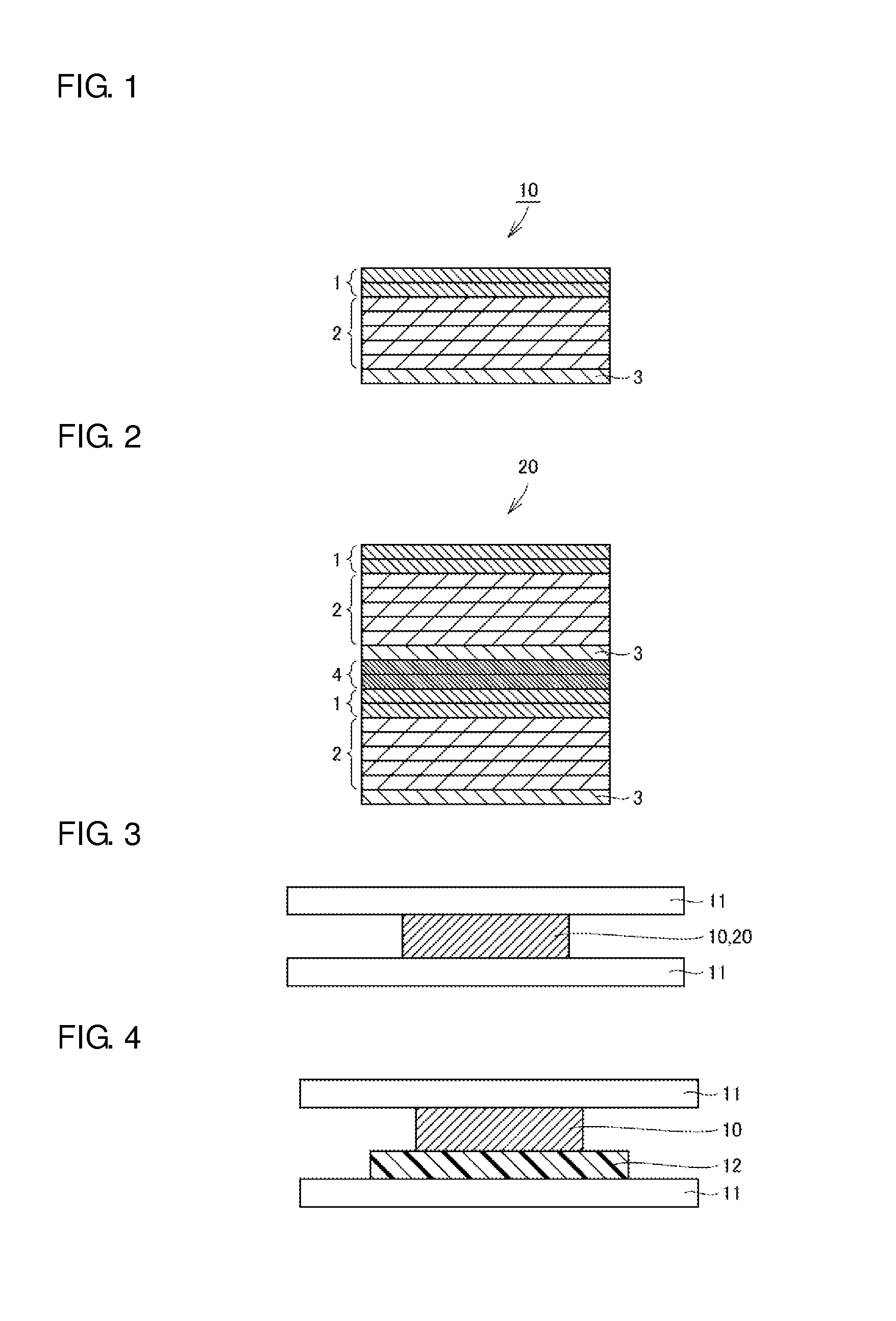
[0078]The stacked body 10 was formed through sequential thermocompression bonding by sandwiching the green sheets between two stainless-steel flat plates 11 as shown in FIG. 3 or 4, every time each of the green sheets peeled from the PET film was stacked.
[0079]In this case, in the comparative example, the stacked body 10 was formed through sequential thermocompression bonding by sandwiching the stacked green sheets directly between the two stainless-steel flat plates 11 as shown in FIG. 3. In Examples 1 to 5, the stacked body 10 was formed through sequential thermocompression bonding, each with a polyester film 12 varying in surface roughness [μmRa] as shown in Table 1 below, which is interposed between the lower stainless-steel flat plate 11 and the stacked green sheets as shown in FIG. 4. The thermocompression bonding was carried out by heating the stainless-steel flat plates 11 to a temperature of 60° C., and applying a pressure of 2000 kg / cm2.
[0080]It is to be...
examples 6 to 7
[0081]The stacked body 10 was formed through sequential thermocompression bonding by sandwiching the green sheets directly between two stainless-steel flat plates 11 as shown in FIG. 3, every time each of the green sheets peeled from the PET film was stacked. The thermocompression bonding was carried out by heating the stainless-steel flat plates 11 to a temperature of 60° C., and applying a pressure of 1000 kg / cm2.
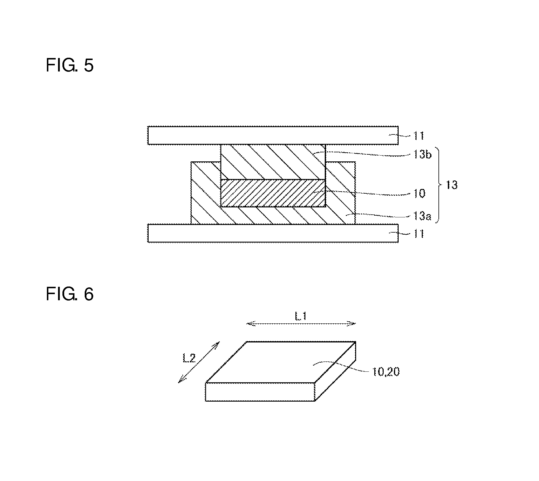
[0082]Next, in order to adequately enhance the adhesion between the respective green sheets constituting the stacked body 10, pressure was applied with the stacked body 10 sandwiched between the two stainless-steel flat plates 11. In this case, pressure was applied to the stacked body 10, each with a polyester film 12 varying in surface roughness [μmRa] as shown in Table 1 below, which is interposed between the lower stainless-steel flat plate 11 and the stacked body 10 as shown in FIG. 4. While the stainless-steel flat plates 11 were kept at room temperature without heat...
PUM
| Property | Measurement | Unit |
|---|---|---|
| Temperature | aaaaa | aaaaa |
| Temperature | aaaaa | aaaaa |
| Fraction | aaaaa | aaaaa |
Abstract
Description
Claims
Application Information
 - Generate Ideas
- Intellectual Property
- Life Sciences
- Materials
- Tech Scout
- Unparalleled Data Quality
- Higher Quality Content
- 60% Fewer Hallucinations
Browse by: Latest US Patents, China's latest patents, Technical Efficacy Thesaurus, Application Domain, Technology Topic, Popular Technical Reports.
© 2025 PatSnap. All rights reserved.Legal|Privacy policy|Modern Slavery Act Transparency Statement|Sitemap|About US| Contact US: help@patsnap.com