Unit cell for solid oxide electrolyte type fuel cell and related manufacturing method
- Summary
- Abstract
- Description
- Claims
- Application Information
AI Technical Summary
Benefits of technology
Problems solved by technology
Method used
Image

Examples
example 1
[0068]In this EXAMPLE 1, a SOFC unit cell was prepared to have a structure that included the porous base body 1 and the battery components (the electrode 10, the solid electrolyte 12 and the electrode 11) shown in EXAMPLE 1 of FIGS. 10A and 10B.
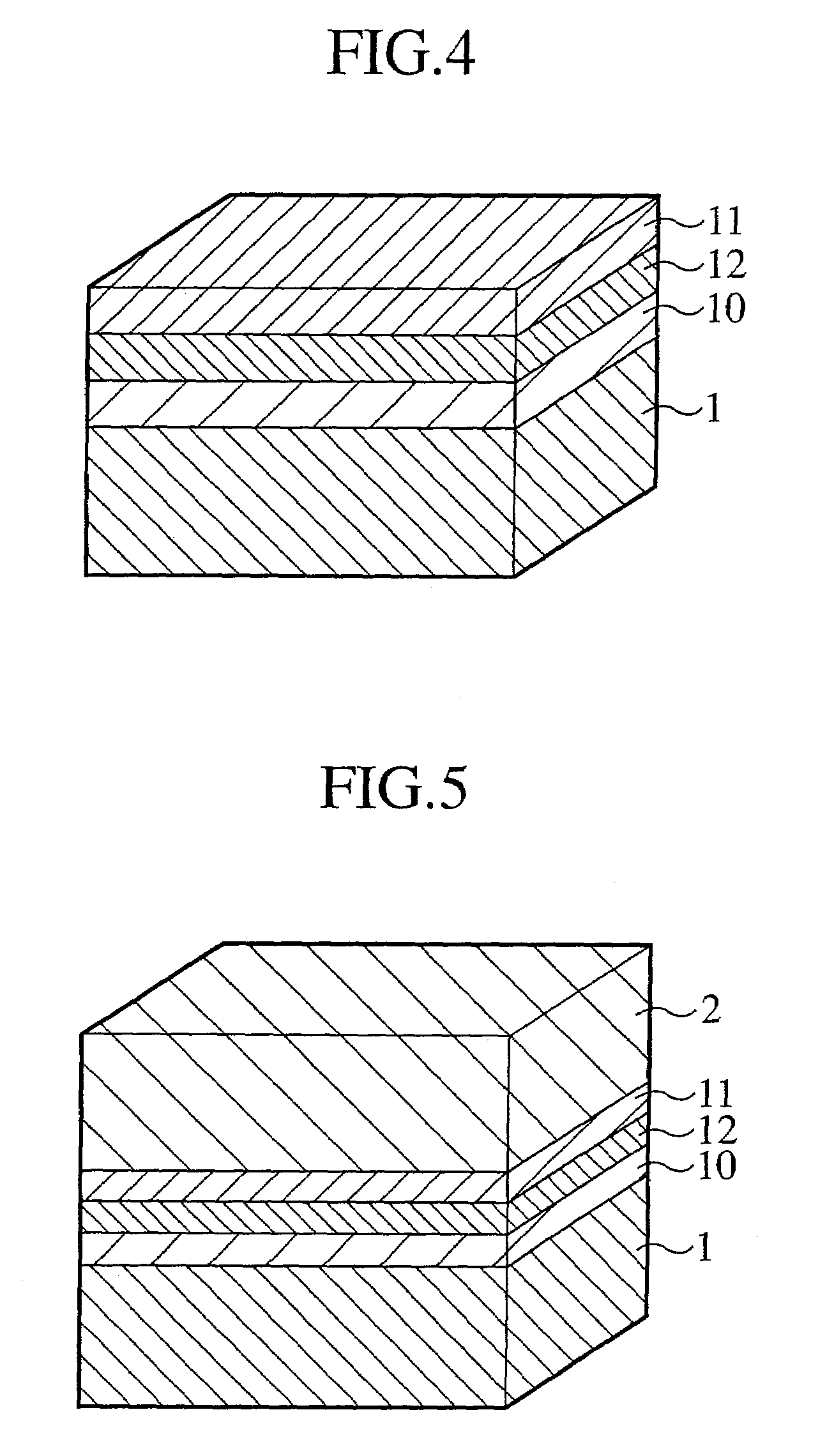
[0069]In particular, as shown in FIGS. 8A and 8B, the porous base body 1, which includes a ceramic (alumina) body plated with Ni, is coated with the electrode 10 (Ni-8% YSZ), the solid electrolyte 12 (8% YSZ) and the electrode 11 (LSC) in a sequence using the screen printing process, with the porous base body 2, which includes a ceramic body plated with Ag, being placed on the electrode 11 and heated at the temperature of 850° C. and pressed under a pressure 10 Pa thereby obtaining the SOFC unit cell as shown in FIG. 5. Also, the porous base body 1 had the first and second surface layers which were different from one another in thickness, the pore diameter and the pore rate, while the porous base body 2 also had the first and second surface l...
example 2
[0071]In this EXAMPLE 2, a SOFC unit cell was prepared to have a structure that included the porous base body 1 and the battery components (the electrode 10, the solid electrolyte 12 and the electrode 11) shown in EXAMPLE 2 of FIGS. 10A and 10B.
[0072]In particular, this Example 2, the SOFC was prepared in the same process as that of the Example 1 and had the same structure as that of the Example 1 except for a slight alteration in that the sintered bodies of metallic fine grains (Ni-16Cr-8Fe) were used as the porous base bodies 1 and 2 and the solid electrolytes were coated over these components by sputtering such that the thickness, the pore diameters and the pore rates of the porous base bodies 1 and 2 and the thickness of the battery components 10 to 12 were altered.
[0073]Such a SOFC unit cell also had an electric power generating characteristic and durability for an adequate practical use.
example 3
[0074]In this EXAMPLE 3, a SOFC unit cell was prepared to have a structure that included the porous base body 1 and the battery components (the electrode 10, the solid electrolyte 12 and the electrode 11) shown in EXAMPLE 3 of FIGS. 10A and 10B.
[0075]In particular, as shown in FIGS. 9A and 9B, the porous base body 1, which includes a metallic fiber sintered body (composed of a sheet of Fe-20Cr-5Al), is coated with the electrode 10 (Ni-8% YSZ) and the solid electrolyte 12 (8% YSZ) in a sequence using the screen printing process, while on the other hand, the porous base body 2 (composed of the metallic fiber body (the sheet of Fe-20Cr-5Al) was coated with the electrode 11 (LSC) by screen printing whereupon the porous base bodies 1 and 2 were heated at the temperature of 850° C. and pressed with respect to one another under a pressure 10 Pa such that the solid electrolyte 12 and the electrode 11 were opposed to one another thereby obtaining the SOFC unit cell as shown in FIG. 5. Also, ...
PUM
 Abstract
Description
Claims
Application Information
 - Generate Ideas
- Intellectual Property
- Life Sciences
- Materials
- Tech Scout
- Unparalleled Data Quality
- Higher Quality Content
- 60% Fewer Hallucinations
Browse by: Latest US Patents, China's latest patents, Technical Efficacy Thesaurus, Application Domain, Technology Topic, Popular Technical Reports.
© 2025 PatSnap. All rights reserved.Legal|Privacy policy|Modern Slavery Act Transparency Statement|Sitemap|About US| Contact US: help@patsnap.com